SF_EDM (External Device Monitoring)
The following description is valid for the function block SF_EDM_V1_0z, Version 1.0z (where z = 0 to 9).
Short description
|
The safety-related SF_EDM (External Device Monitoring) function block monitors the defined initial state and the switching behavior of contactors connected to the Safety Logic Controller. S_StartReset can be used to specify a start-up inhibit. |
|
| WARNING | |
|---|---|
Function block inputs
Click the corresponding hyperlinks to obtain detailed information on the items below.
|
Name |
Short description |
Value |
|---|---|---|
|
State-controlled input for activating the function block. Data type: BOOL Initial value: FALSE |
|
|
|
State-controlled input for controlling contactors connected to the S_EDM_Out function block output. Data type: SAFEBOOL Initial value: SAFEFALSE |
|
|
|
State-controlled inputs for feedback signals from the connected contactors. Data type: SAFEBOOL Initial value: SAFEFALSE
NOTE:
If only one feedback signal is used, this must be connected in parallel to both inputs S_EDM1 and S_EDM2. Both inputs must show the SAFETRUE state (initial state of the contactors) for the function block to be able to switch the S_EDM_Out output to SAFETRUE. |
|
|
|
Input for specifying the maximum response time for the switching operations of the connected contactors. Data type: TIME Initial value: #0ms The switching operations are evaluated via the S_EDM1 and S_EDM2 inputs. If the specified response time has been exceeded, the Error output is switched to TRUE and the S_EDM_Out output is switched to SAFEFALSE as a result. |
Enter a time value according to your risk analysis. Refer to the first hazard message below this table. |
|
|
Input for specifying the start-up inhibit after the Safety Logic Controller has been started up or the function block has been activated. Data type: SAFEBOOL Initial value: SAFEFALSE An active start-up inhibit must be removed manually by means of a positive signal edge at the Reset input. A deactivated start-up inhibit causes the S_EDM_Out output to switch to SAFETRUE automatically when the function block is activated and the safety-related function is not requested. Refer to the second hazard message below this table. |
|
|
|
Edge-triggered input for the reset signal:
Refer to the third hazard message below this table. Data type: BOOL Initial value: FALSE
NOTE:
Resetting does not occur with a negative (falling) edge, as specified by standard EN ISO 13849-1, but with a positive (rising) edge. |
|
| WARNING | |
|---|---|
| WARNING | |
|---|---|
Resetting the function block by means of a positive signal edge at the Reset input can cause the S_EDM_Out output to switch to SAFETRUE immediately (depending on the status of the other inputs).
| WARNING | |
|---|---|
Function block outputs
|
Name |
Short description |
Value |
|---|---|---|
|
Output for signaling "Function block activated/not activated". Data type: BOOL |
|
|
|
Output for the signal to control the connected contactors. Data type: SAFEBOOL |
|
|
|
Output for error message. Data type: BOOL |
|
|
|
Output for diagnostic message. Data type: WORD |
Diagnostic message of the function block. The possible values are listed and described in the topic "Diagnostic codes". |
Signal sequence diagram
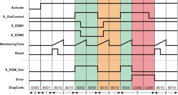
This diagram is based on a typical interconnection with a start-up inhibit after the function block has been activated or the Safety Logic Controller has started up (S_StartReset = SAFEFALSE).
The signal sequence diagrams in this documentation possibly omit particular diagnostic codes. For example, a diagnostic code is possibly not shown if the related function block state is a temporary transition state and only active for one cycle of the Safety Logic Controller.
Only typical input signal combinations are illustrated. Other signal combinations are possible.
The other signal sequence diagram can be taken into account.
|
0 |
The function block is not yet activated (Activate = FALSE). As a result, all outputs are FALSE or SAFEFALSE. |
|
1 |
After the function block has been activated by Activate = TRUE, the start-up inhibit is active at first. |
|
2 |
When the FALSE > TRUE edge applies at the Reset input, the start-up inhibit is removed and the time set at MonitoringTime for the two inputs S_EDM1 and S_EDM2 is started. The monitoring time expires without result, as inputs S_EDM1 and S_EDM2 are both SAFETRUE. |
|
3 |
The feedback signals at inputs S_EDM1 and S_EDM2 report the initial state of the contactors (S_EDM1 and S_EDM2 are SAFETRUE). In this state, S_OutControl = SAFETRUE. Monitoring time measurement begins at this point and the S_EDM_Out output becomes SAFETRUE. Both feedback signals S_EDM1 and S_EDM2 switch to SAFEFALSE during the time set at MonitoringTime. Consequently, both monitored contactors function correctly, so that the S_EDM_Out output remains SAFETRUE and the Error output remains FALSE. |
|
4 |
The state at the S_OutControl input switches to SAFEFALSE, which results in the S_EDM_Out output switching to SAFEFALSE. Monitoring time measurement starts again with the state change at S_EDM_Out. Both feedback signals S_EDM1 and S_EDM2 switch to SAFETRUE correctly during the time set at MonitoringTime (initial state of the contactors). As a result, the Error output remains FALSE. |
|
5 |
The S_OutControl input becomes SAFETRUE, which switches the S_EDM_Out output to SAFETRUE. At this time, both the feedback signals S_EDM1 and S_EDM2 = SAFETRUE (initial state of the connected contactors). The timer set at MonitoringTime starts when the S_EDM_Out output switches to SAFETRUE. The feedback signals at inputs S_EDM1 and S_EDM2 do not switch to SAFEFALSE during the monitoring time, as the connected contactors may be inoperable, for example. After the time set at MonitoringTime has elapsed, output Error = TRUE and output S_EDM_Out = SAFEFALSE. |
|
6 |
The error message is reset (Error becomes FALSE) when the positive edge applies at the Reset input. This signal edge also starts the timer set at MonitoringTime. The monitoring time expires without result, as the feedback signals at the inputs S_EDM1 and S_EDM2 are still SAFETRUE. |
Application example
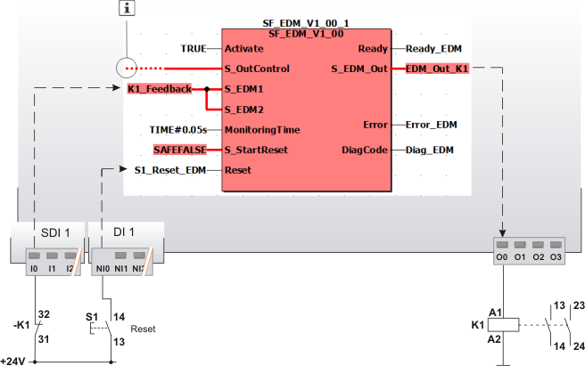
In this example, the safety-related SF_EDM function block monitors the switching behavior of a contactor K1 connected at output terminal O0 of the Safety Logic Controller.
Via input terminal I0 of the safety-related input device SDI 1, an N/C contact provides single-channel feedback signal from the contactor to the S_EDM1 and S_EDM2 inputs (single-channel application up to Cat. 2). The resulting signal of the input terminal is assigned to the global I/O variable K1_Feedback.
The reset button S1 is connected to the input terminal NI0 of the standard input device DI 1. The signal at input terminal NI0 assigned to the global I/O variable S1_Reset_EDM is used to remove the start-up inhibit and reset the error states after the cause of the error has been removed.
The S_OutControl input is controlled by another safety-related function block or a safety-related function within the program.
|
K1 |
Contactor or relay with positively driven contacts. |
|
S1 |
Reset |
|
|
See note above the illustration. |

The other application examples and the accompanying notes can be taken into account.
Detailed information
Additional information is available in the following sections: