The TM262L20MESE8T logic controller has:
o4 fast digital inputs
o4 fast digital outputs (source)
oCommunication ports:
o1 serial line port
o1 USB mini-B programming port
o2 Ethernet switched ports
o1 Ethernet port
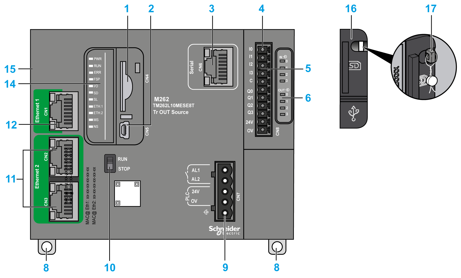
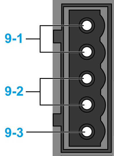
The following figure shows the different components of the TM262L20MESE8T logic controller:


|
N° |
Description |
Refer to |
|---|---|---|
|
1 |
SD card slot |
|
|
2 |
USB mini-B programming port for terminal connection to a programming PC (EcoStruxure Machine Expert) |
|
|
3 |
Serial line port / type RJ45 (RS-232 or RS-485) |
|
|
4 |
Inputs/outputs terminal connector |
|
|
5 |
TM3 bus connector |
|
|
6 |
I/O status LEDs |
|
|
8 |
Clip-on lock for 35 mm (1.38 in.) top hat section rail (DIN rail) |
|
|
9-1 |
Alarm relay terminal connector |
|
|
9-2 |
24 Vdc power supply |
|
|
9-3 |
Functional Earth (FE) grounding connection |
|
|
10 |
Run/Stop switch |
|
|
11 |
Dual port Ethernet switch |
|
|
12 |
Ethernet port 1 |
|
|
14 |
Status LEDs |
See below |
|
15 |
TMS bus connector |
|
|
16 |
Protective cover (for SD card slot and USB mini-B programming port) |
- |
|
17 |
Locking hook (optional lock not included) |
- |
This figure shows the status LEDs:

The following table describes the system status LEDs:
|
Label |
Function Type |
Color |
Status |
Description |
||
|---|---|---|---|---|---|---|
|
PWR |
Power |
Green/Red |
Green OFF/Red OFF |
Indicates that power is removed. |
||
|
Green ON/Red OFF |
Indicates that power is applied, normal operation. |
|||||
|
Green ON/Red 1 flash |
Elevated internal operating temperature detected. Take appropriate measures to reduce the temperature. |
|||||
|
Green ON/Red 2 flashes |
Detected error on TM3 power. |
|||||
|
Green ON/Red 3 flashes |
Detected error on TMS power. |
|||||
|
Green ON/Red 4 flashes |
Detected error on Serial line power. |
|||||
|
RUN |
Machine status |
Green |
ON |
Indicates that the controller is running a valid application. |
||
|
Regular flash |
Indicates that the controller is running a valid application that is stopped. |
|||||
|
Single flash |
Indicates that the controller is running a valid application that is stopped at a breakpoint. |
|||||
|
OFF |
Indicates that the controller does not contain a valid application. |
|||||
|
ERR |
Internal Error |
Red |
ON |
Indicates that an application error (exception) has been detected. The RUN LED is flashing to indicate that the application is stopped. |
||
|
Fast flash |
Indicates that the controller has detected a firmware error. |
|||||
|
Regular flash |
Indicates either that a minor error has been detected if RUN is ON or flashing regularly, or that no application has been detected if RUN is OFF. |
|||||
|
FSP |
Forced stop |
Red |
ON |
Indicates that the Run/Stop switch or Run/stop input has been activated to force the controller to the STOPPED state. |
||
|
Regular flash |
Indicates that at least one application variable is being forced. |
|||||
|
I/O |
I/O error |
Red |
ON |
Indicates that I/O or expansion module errors have been detected. More details on the error detected are provided by the system variables i_lwSystemFault_1 and i_lwSystemFault_2, and on the Diagnostics tab of the controller Web site. |
||
|
SD |
SD card access |
Green |
ON |
Indicates that a firmware update is in progress. |
||
|
Green |
Regular flash |
Indicates that a firmware update or script execution is in progress. |
||||
|
Yellow |
ON |
Indicates that a firmware update or script execution failed. |
||||
|
Yellow |
Regular flash |
Indicates that the SD card is being accessed (script execution in progress). |
||||
|
- |
OFF |
No SD card activity. |
||||
|
SL |
Serial line |
Green |
ON |
Indicates activity on the serial line. |
||
|
OFF |
Indicates no serial communication. |
|||||
|
ETH.1 ETH.2 |
Ethernet port status |
Green |
ON |
Indicates that the Ethernet port is connected and the IP address is defined. |
||
|
3 flashes |
Indicates that the Ethernet port is not connected. |
|||||
|
4 flashes |
Address conflict detected. Indicates that the configured IP address is already in use. |
|||||
|
5 flashes |
Indicates that the address is the default address. The module is waiting for a BOOTP or DHCP sequence. |
|||||
|
6 flashes |
Indicates that the configured IP address is not valid. The default IP address is being used. |
|||||
|
OFF |
Indicates that the Ethernet port is not configured. |
|||||
|
MS |
EtherNet/IP controller interface status |
Red |
ON |
Indicates that an unrecoverable error has been detected. |
||
|
Regular flash |
Indicates that a recoverable error has been detected. |
|||||
|
Green |
ON |
Indicates that the controller interface is functioning normally. |
||||
|
Regular flash |
Indicates that the configuration is missing, incomplete, or incorrect. |
|||||
|
Red/Green |
Regular flash |
Indicates that an error has been detected. |
||||
|
- |
OFF |
Indicates that the controller is powered off. |
||||
|
NS |
EtherNet/IP network status |
Red |
ON |
Indicates that one or more connections timed out, or that an error is preventing network communications (duplicate IP address, or bus powered off) |
||
|
Regular flash |
Indicates that a recoverable error has been detected, for example, one or more connections timed out. |
|||||
|
Green |
ON |
Indicates that the controller interface is functioning normally and network connections are established. |
||||
|
Regular flash |
Indicates that the controller interface is operating normally, but network connections have not been established, or the network configuration is missing, incomplete, or incorrect. |
|||||
|
Red/Green |
Regular flash |
Indicates that an error has been detected. |
||||
|
- |
OFF |
Indicates that the controller is powered off. |
||||
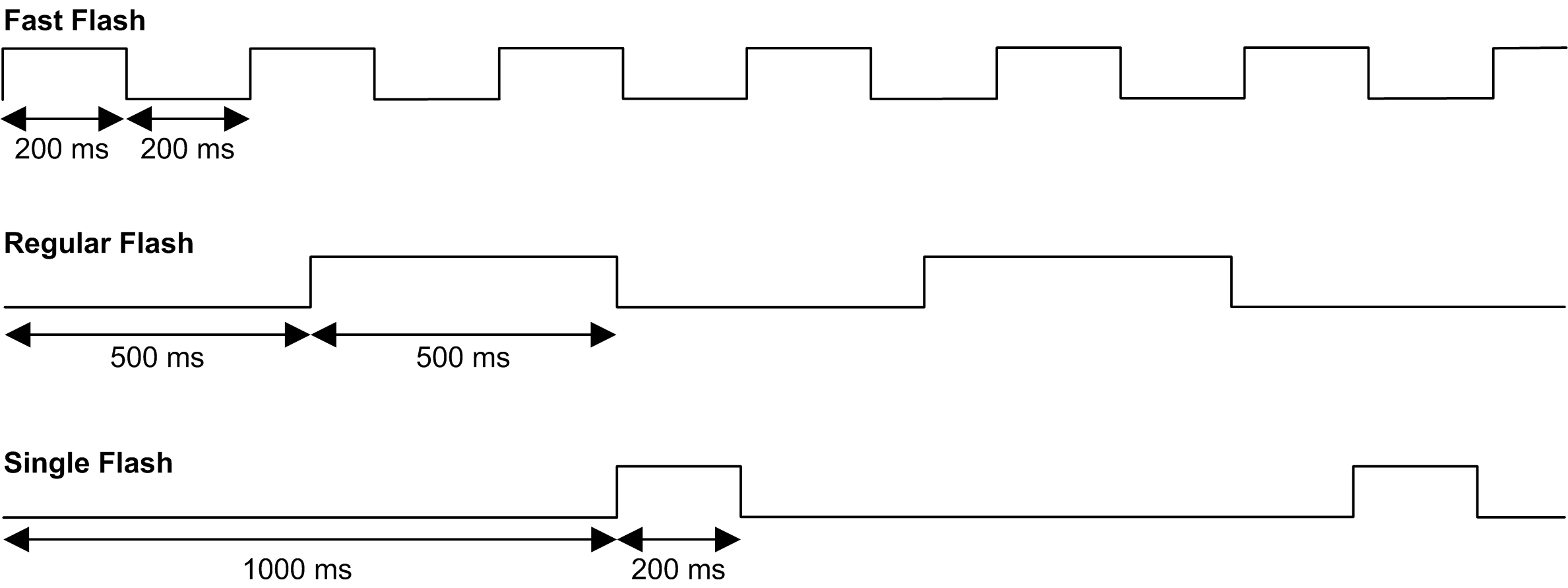
This timing diagram shows the difference between the fast flash, regular flash and single flash:

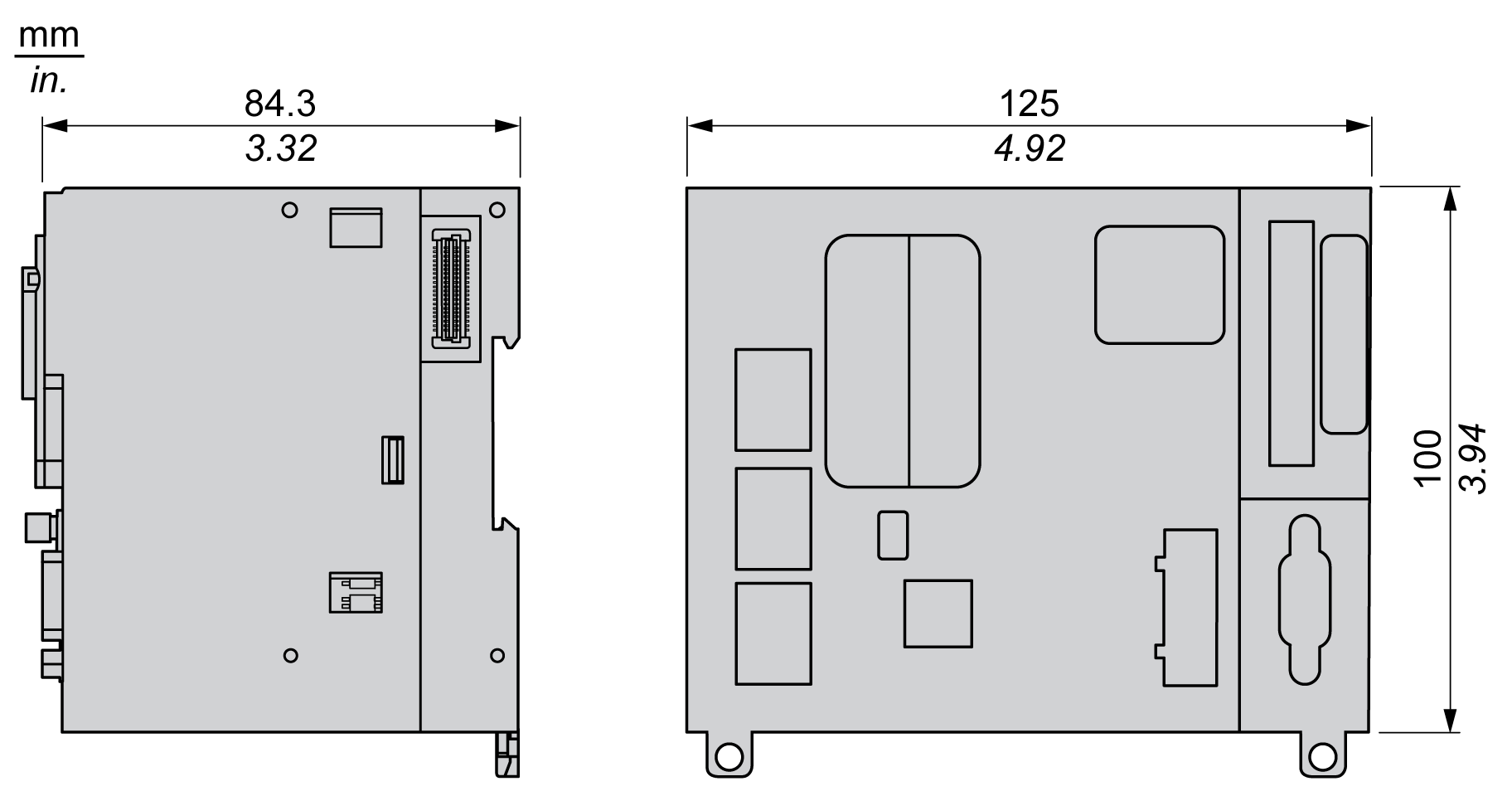
The following figure shows the external dimensions of the TM262L20MESE8T logic controller:
