TM5SAI4AFS Analog Current Input Safety Module (SLCv2)
This topic applies to an SLCv2 generation module (in a safety-related system with an SLC300 or SLC400 device). Which device generation is configured in your project is visible at the end of the short device description above the parameter grid (while the device is selected in the tree on the left).
Module type/safety-related fields of application
Analog current input safety-related module, 2x2 safety-related analog input channels, 4 to 20 mA, 24 bit converter resolution, each channel electrically isolated, equivalence evaluation for two-channel applications.
Input filter and switching threshold configurable by software.
Schneider Electric safety-related modules can be used in safety-related applications according to:
-
EN ISO 13849, PL e
-
IEC 62061, SIL 3
-
IEC 61508, SIL 3
Group: Basic
Parameter: MinRequiredFWRev
|
Default value |
Basic Release |
|
Unit |
-/- |
|
Description |
This parameter is only relevant in case of implementing other firmware versions than the manufacturer-loaded version. To enter the operational state, the firmware version parameterized here or a newer version must be installed on the module.
The firmware version selected here is particularly important with regard to parameters or process data items that have been implemented with a particular firmware version. If the device you are currently working with has new parameters or process data items, the following applies: if MinRequiredFWRev is set to an incorrect value, either the SLC will not enter the operational run status or the new parameters/process data items will not be taken into account by the SLC. Refer to the hazard message below this table.
Further Information:
Information on newly added parameters or process data items can be found in the Release Notes you received with the firmware package. The Release Notes also describe how to determine the firmware version that is currently installed on the safety-related device. |
| WARNING | |
|---|---|
Parameter: Optional
|
Default value |
No |
|
Unit |
-/- |
|
Description |
The module can be configured as optional using this parameter. Optional modules do not have to be available (physically present or communicative), i.e., if an optional module is unavailable, this is not signaled by the Safety LogicController. This parameter does not influence the module signal or status data. |
|
Possible values |
|
The Optional parameter is a mechanism to scale your safety-related system for various configurations of your machine design. However, it may be the case that the module(s) that you have designated as optional may be required in some of your alternative machine configurations.
| WARNING | |
|---|---|
Parameter: InputFilter
|
Default value |
1 |
|
Possible values |
Selectable from drop-down list: 1; 2; 10; 16.7; 20; 33.3; 40; 66.7 |
|
Unit |
ms |
|
Description |
Configures the input filter by defining the sample interval of the A/D converter. The parameter sets the interval for sampling the analog value at the module inputs. During this interval, values are captured. The related output process data item is updated after the sampling interval has elapsed. By defining the input update interval, this value directly influences the signal processing time of the module and consequently the safety response time of the entire input-output channel of the safety-related application. Refer to the information below this table. |
Impact of the set filter value on the safety response time
The following table lists the signal processing time of the module resulting from the set input filter time value (update interval).
| WARNING | |
|---|---|
|
Configured filter value |
Max. signal processing time of the module |
|---|---|
|
1 ms |
17 ms |
|
2 ms |
19 ms |
|
10 ms |
35 ms |
|
16.7 ms |
50 ms |
|
20 ms |
55 ms |
|
33.3 ms |
82 ms |
|
40 ms |
95 ms |
|
66.7 ms |
122 ms |
Group: SafetyResponseTime
The safety response time is the time between the arrival of the sensor signal on the input channel of a safety-related input module and the shut-off signal at the output channel of a safety-related module. For further and detailed background information, refer to the topic "Safety Response Time for SLCv2 " in the "Machine Expert – Safety - User Guide".
The parameters in this group influence the safety response time of the Safety Logic Controller system. The parameters SafeDataDuration and ToleratedPacketLoss in this group are only applied to the module if ManualConfiguration is set to 'Yes'.
Parameter: ManualConfiguration
|
Default value |
No |
|
Unit |
-/- |
|
Description |
Specifies whether the module uses its safety response time-relevant parameters (SafeDataDuration and ToleratedPacketLoss) or the values specified in the 'SafetyResponseTimeDefaults' parameter group of the Safety Logic Controller. Managing parameters per module optimizes the system to application-specific requirements regarding the safety response time. |
|
Parameter value |
|
Parameter: SafeDataDuration
|
Default value |
200 |
|
Value range Step size |
25...9,380 1 |
|
Unit |
100 µs |
|
Description |
This parameter influences the safety response time of the safety-related application. Specifies the maximum permissible time for data transmission from a safety-related producer to a consumer, that is, from an input module to the SLC, or from the SLC to an output module. Based on this parameter value and the value of the 'ToleratedPacketLoss' parameter (described below), and further module-specific processing times, the Safety Response Time (SRT) is calculated. Verify the SRT resulting from the parameter values entered here using the 'Response Time Calculator' dialog in Machine Expert – Safety (menu item 'Project > Response Time Calculator'). |
|
Value calculation |
The risk analysis you have performed for your safety-related application delivers the maximum allowed overall response time of the safety function and, as part of this, the safety function response time (SRT) of the signal chain. The SRT is composed of the following partial time values:
with
(including configured filter/delay times),
(including configured delay times),
This maximum SRT value is the basis for the calculation of the SafeDataDuration (SDD) and the ToleratedPacketLoss (TPL) value you must enter as the parameter value in the grid. From the allowed SRT, deduct the processing times of the safety-related input module (SPTi) and the output module (SPTo). The result is the total maximum permissible time for the safety-related data transmission on the complete safety-related path, i.e., from the input module to the output module. As the SafeDataDuration parameter relates to only one transmission path (input module -> SLC or SLC -> output module), you must divide the value by 2 to get the required value to be entered in the parameter grid. If a packet loss greater than 0 is tolerated, this must also be considered. The calculation equation is as follows:
With
|
Parameter: ToleratedPacketLoss
|
Default value |
1 |
|
Value range Step size |
0...10 1 |
|
Unit |
Data packets |
|
Description |
Specifies the maximum allowed number of lost packets during data transmission. The number of tolerated packet losses affects the safety response time. Based on this parameter value and the value of the 'SafeDataDuration' parameter, the Safety Response Time (SRT) of the system is calculated. Verify the SRT resulting from the parameter values entered here using the 'Response Time Calculator' dialog in Machine Expert – Safety (menu item 'Project > Response Time Calculator'). |
Group: SafeCurrentxxyy
In this group, the four parameters with the same index number (1 to 4) are considered as parameter set. Which parameter set is active on the module depends of the channel settings 'SafeThrSelector_0y0z_Bit1' and 'SafeThrSelector_0y0z_Bit2'. By activating a particular parameter set thus adjusting the input sensitivity, the module can be adapted for the present use case. Refer to the section "Process data items: SafeThrSelector_0y0z_Bit1 and SafeThrSelector_0y0z_Bit2" below for details and information how to switch the parameter set.
Parameters LimitThresholdHigh_Set1 to LimitThresholdHigh_Set4
|
Default value |
20,000 |
|
Value range Step size |
3,600...21,000 1 |
|
Unit |
µA |
|
Description |
Specifies the maximum permissible input value for each channel of the module. Exceedance of the specified input value range can be monitored by evaluating the SafeCurrentOKxx process data item of the respective channel in the safety-related application. This process data item is SAFETRUE as long as the measured value is within the parameterized value range, otherwise it switches to SAFEFALSE. Verify that the maximum value set here is greater than the minimum value set with the LimitThresholdLow* parameter. |
Parameters LimitThresholdLow_Set1 to LimitThresholdLow_Set4
|
Default value |
4,000 |
|
Value range Step size |
3,600...21,000 1 |
|
Unit |
µA |
|
Description |
Specifies the minimum permissible input value for each channel of the module. Exceedance of the specified input value range can be monitored by evaluating the SafeCurrentOKxx process data item of the respective channel in the safety-related application. This process data item is SAFETRUE as long as the measured value is within the parameterized value range, otherwise it switches to SAFEFALSE. Verify that the minimum value set here is less than the maximum value set with the LimitThresholdHigh* parameter. |
Parameters LimitThresholdEquivalent_Set1 to LimitThresholdEquivalent_Set4
This parameter is only relevant in two-channel applications. When connecting two sensors as input pair, the module automatically evaluates the equivalence of the input signals.
|
Default value |
20,000 |
|
Value range Step size |
0...21,000 1 |
|
Unit |
µA |
|
Description |
Specifies the maximum permissible value difference between both input channels of an input pair in two-channel applications. Violation of the specified equivalent threshold after the set discrepancy time has elapsed (see next parameter DiscrepancyTime*) can be monitored by evaluating the SafeCurrentOKxxyy process data item of the respective channels in the safety-related application. In case of exceedance, this process data item switches to SAFEFALSE. |
Parameters DiscrepancyTime_Set1 to DiscrepancyTime_Set4
This parameter is only relevant in two-channel applications. When connecting two sensors as input pair, the module automatically evaluates the equivalence of the input signals.
|
Default value |
0 |
|
Possible values |
Selectable from drop-down list: 0; 2; 5; 10; 20; 50; 100; 200; 500; 1,000; 2,000; 5,000; 10,000 |
|
Unit |
ms |
|
Description |
Specifies the maximum time interval during which the difference between both channels of an input pair in two-channel applications may exceed the limit value without triggering an error. Violation of the parameterized discrepancy time can be monitored by evaluating the SafeCurrentOKxxyy process data item of the respective channels in the safety-related application. In case of exceedance, this process data item switches to SAFEFALSE. |
Parameter: DisableShunttest
|
Default value |
No |
|
Unit |
-/- |
|
Description |
Enables or disables the automatic shunt test of the measurement shunts. Disabling the shunt test increases the tolerance of the module regarding input signal interferences. The parameter sets the behavior for all input channels of the module. |
|
Possible values |
|
Parameter: MeasurementResultWhileTesting
This parameter is available with device firmware version V322 or greater. Make sure that the MinRequiredFWRev parameter of this module is set to 'Basic Release from FW V322' in order to use the MeasurementResultWhileTesting parameter correctly.
|
Default value |
Single Channel |
|
Unit |
-/- |
|
Description |
The parameter sets the behavior of the module, i.e., the measurement mode during the internal hardware channel test. Each measurement channel is tested electronically by applying an internal test signal to the channel periodically every 75 minutes. The test signal is applied for a maximum of one second. Only one channel is tested at a time while the other channel continues the normal analog value measurement. During the test period, the last measured value of the tested channel is retained (fixed) until the test is completed. Then, normal measurement is continued on both channels until the other channel is tested. While no test is active, the resulting value is calculated as follows (see also the description of the process data item below): Resulting value = (value channel xx + value channel yy)/2. Using the MeasurementResultWhileTesting parameter, the calculation mode during the test period can be set.
NOTE:
Use the diagnostic process data item TestActive (see description below) to signal and evaluate the active test in the safety-related application. |
|
Possible values |
|
Process data items of the module
Purpose and use of process data items
Each module provides process data items (signals). Process data items can be:
-
I/O signals delivered from or written to a module terminal.
-
diagnostic signals for evaluating the status of input/output channels or the entire module.
-
control signals, for example, for enabling a channel or adjusting the module.
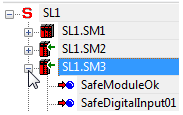
The available process data items of a module are listed under the module node in the tree on the left of the 'Devices' window. To display and use the process data items, expand the module node in the tree by clicking the '+' symbol.
Example
The module with the ID SL1.SM3 provides (among others) the diagnostic signal SafeModuleOK and the input signal SafeDigitalInput01.
From the devices tree, process data items can be inserted into the safety-related FBD/LD code by drag & drop (see following procedure). On insertion into the code, a standard (non-safety-related) or safety-related global variable is created (depending on the data type of the process data item).
Procedure: How to insert process data items into the code
-
Open the code worksheet where you want to insert the process data item and create/use the global variable assigned to it.
-
In the 'Devices' window, open the devices tree on the left and expand the module (tree node) which contains the process data item to be used.
-
Drag the process data item into the code worksheet. When releasing the mouse button, the 'Variable' dialog appears.
To insert a Boolean variable as a contact into the graphical code, hold the <CTRL> key down when releasing the mouse button after dragging the variable from the device terminal grid into the code worksheet.
-
In the 'Variable' dialog, a default name is proposed which is derived from the process data item name. Accept the proposed name, select an existing global variable, or declare a new global variable by entering a new 'Name', defining the 'Data Type' and selecting a 'Group'.
-
Confirm the 'Variable' dialog by clicking 'OK'.
The rectangle shape of the variable is now added to the cursor. It can be dropped at the desired position with a click. You can directly connect the variable to another object (e.g., a formal parameter as shown in the following example) or dropped at any free position.
Data direction depends on the signal type
Input signals can only be read and output signals can be written by the safety-related application.
Diagnostic signals can be used to evaluate and monitor the status of the safety-related module or individual I/O channels, for example. Therefore, global variables created for and assigned to diagnostic signals can be read by the application.
Control signals can be used to enable the module operation or to adjust/adapt the module for the present use case (for example, by setting a measurement range or a particular module behavior). The global variables created for and assigned to control signals can be written by the application, thus controlling the module.
Representation of the process data items in the devices tree:
|
Icon |
Signal type |
Access type |
|---|---|---|

|
Safety-related input signal or diagnostic signal. |
read |

|
Non-safety-related input signal (only available for the Safety Logic Controller). |
read |

|
Non-safety-related output signal (only available for the Safety Logic Controller) or control signal. |
write |

|
Safety-related output or control signal. |
write |
If a standard (non-safety-related) signal is connected to a physical input or output, the data type of the corresponding global variable must be modified from safety-related to standard (e.g., from SAFEBOOL to BOOL) to rule out an incorrect use of the signal in the code. The same applies if a safety-related signal is used only as standard signal in the code. Modifying the data type can either be done in the appropriate variables worksheet or using type converter functions.
| WARNING | |
|---|---|
In the following, the I/O, diagnostic and control signals of the present module are listed and described in the order they are listed in the devices tree.
SafeModuleOK
|
Description |
Indicates the status of the communication between the safety-related module and the Safety Logic Controller and therefore, from safety-related application perspective, the module status itself. |
|
Signal type |
Diagnostic |
|
Data type |
SAFEBOOL |
|
Access type |
Variable can be read by the safety-related application |
|
Possible values |
SAFEFALSE:
SAFETRUE:
|
Mandatory assignment validation for the SafeModuleOK data item:
The verification/validation of the assignment of each process data item to a global I/O variable is mandatory. This particularly applies to the SafeModuleOK process data item which is available for each safety-related module and indicates its status. As the SafeModuleOK data item cannot be written to, e.g., by applying a signal to a module input, the module to be verified must be physically removed from the TM5 bus. As a result, SafeModuleOK switches to SAFEFALSE and the assigned global I/O variable must follow. For further information on the steps to remove and reinsert a module, refer to the user manual of the module.
| WARNING | |
|---|---|
SafeChannelOKxx (relating to input channels)
|
Description |
Diagnostic signal which indicates the status of the safety-related input channel. xx specifies the channel number. This diagnostic signal confirms the validity of the SafeDigitalInputxx signal. Depending on the results of the risk analysis you carried out for your application, the diagnostic signal must be evaluated each time the SafeDigitalInputxx signal is used in the safety-related application. The value SAFEFALSE of the diagnostic signal indicates an invalid SafeDigitalInputxx value. In this case, the SafeDigitalInputxx signal must not be further used, processed, or evaluated in the safety-related application. Refer to the hazard message below this table.
NOTE:
To detect error status conditions of modules/channels within your application, diagnostic signals must be evaluated in the safety-related code. A programming example and further information can be found in the topic "Monitoring/evaluating diagnostic information of the machine". |
|
Signal type |
Diagnostic signal |
|
Data type |
SAFEBOOL |
|
Access type |
Variable can be read by the safety-related application |
|
Possible values |
SAFEFALSE:
SAFETRUE:
NOTE:
Also observe the respective LED indicator(s) of the affected modules for the error indication. |
| WARNING | |
|---|---|
SafeCurrentOKxx
|
Description |
Diagnostic signal which indicates the status of the current measurement at input channel xx. This diagnostic signal confirms the validity of the incoming analog signal and of the SafeCurrentxx process data item (output measurement value). Depending on the results of the risk analysis you carried out for your application, the diagnostic signal must be evaluated each time the SafeCurrentxx signal is used in the safety-related application. The value SAFEFALSE of the diagnostic signal indicates an invalid SafeCurrentxx value. In this case, the SafeCurrentxx signal must not be further used, processed, or evaluated in the safety-related application. Refer to the hazard message below this table.
NOTE:
To detect error status conditions of modules/channels within your application, diagnostic signals must be evaluated in the safety-related code. A programming example and further information can be found in the topic "Monitoring/evaluating diagnostic information of the machine". |
|
Signal type |
Diagnostic signal |
|
Data type |
SAFEBOOL |
|
Access type |
Variable can be read by the safety-related application |
|
Possible values |
SAFEFALSE: the SafeCurrentxx signal is invalid and must not be used in the safety-related application due to one of the following reasons.
SAFETRUE: the SafeCurrentxx signal is valid. Each of the following conditions must be met:
NOTE:
Also observe the respective LED indicator(s) of the affected modules for the error indication. |
|
Relevant module parameters |
In the parameter group with the same channel number xx:
The related parameter descriptions can be found above in this topic. |
| WARNING | |
|---|---|
SafeCurrentOKxxyy
|
Description |
Diagnostic signal which indicates the status of the two-channel current measurement at input channel pair xx and yy. This diagnostic signal confirms the validity of the incoming analog signal and of the SafeCurrentxxyy process data item (output measurement value). Depending on the results of the risk analysis you carried out for your application, the diagnostic signal must be evaluated each time the SafeCurrentxxyy signal is used in the safety-related application. The value SAFEFALSE of the diagnostic signal indicates an invalid SafeCurrentxxyy value. In this case, the SafeCurrentxxyy signal must not be further used, processed, or evaluated in the safety-related application. Refer to the hazard message below this table.
NOTE:
To detect error status conditions of modules/channels within your application, diagnostic signals must be evaluated in the safety-related code. A programming example and further information can be found in the topic "Monitoring/evaluating diagnostic information of the machine". |
|
Signal type |
Diagnostic signal |
|
Data type |
SAFEBOOL |
|
Access type |
Variable can be read by the safety-related application |
|
Possible values |
SAFEFALSE: the SafeCurrentxxyy signal is invalid and must not be used in the safety-related application due to one of the following reasons.
SAFETRUE: the SafeCurrentxxyy signal is valid. Each of the following conditions must be met:
NOTE:
Also observe the respective LED indicator(s) of the affected modules for the error indication. |
|
Relevant module parameters |
In the parameter groups with the same channel number xx and yy:
The related parameter descriptions can be found above in this topic. |
| WARNING | |
|---|---|
TestActive
This process data item is available with device firmware version V322 or greater. Make sure that the MinRequiredFWRev parameter of this module is set to 'Basic Release from FW V322' in order to use TestActive correctly.
|
Description |
Diagnostic signal which indicates that the internal channel test is currently performed on the module. Each measurement channel is tested electronically by applying an internal test signal to the channel periodically every 75 minutes. The test signal is applied for a maximum of one second. Only one channel is tested at a time while the other channel continues the normal analog value measurement. During the test period, the last measured value of the tested channel is retained (fixed) until the test is completed. Then, normal measurement is continued on both channels until the other channel is tested. Refer to the related module parameter description below.
NOTE:
To detect status conditions of modules/channels within your application, diagnostic signals must be evaluated in the safety-related code. A programming example and further information can be found in the topic "Monitoring/evaluating diagnostic information of the machine". |
|
Signal type |
Diagnostic signal |
|
Data type |
SAFEBOOL |
|
Access type |
Variable can be read by the safety-related application |
|
Possible values |
SAFEFALSE:
SAFETRUE:
|
|
Relevant module parameters |
The MeasurementResultWhileTesting parameter specifies the behavior of the module, i.e., the measurement mode that is applied during the internal hardware channel test. The related parameter description can be found above in this topic. |
SafeCurrentxxyy
|
Description |
Input signal from the sensors connected to the input channel pair xx and yy. Equivalence between the involved channels must be established before the interval specified with the DiscrepancyTime parameter has elapsed. Otherwise, the related diagnostic signal SafeCurrentOKxxyy switches to SAFEFALSE. The validity of this input signal is confirmed by the related diagnostic signals SafeCurrentOKxxyy, SafeChannelOKxx and SafeChannelOKyy. Depending on the results of the risk analysis you carried out for your application, the diagnostic signals must be evaluated each time the SafeCurrentxxyy signal is used in the safety-related application. The value SAFEFALSE of at least one diagnostic signal indicates an invalid SafeCurrentxxyy value. In this case, the SafeCurrentxxyy signal must not be further used, processed, or evaluated in the safety-related application. Refer to the hazard message below this table. |
|
Signal type |
I/O signal |
|
Data type |
SAFEINT |
|
Access type |
Variable can be read by the safety-related application |
|
Possible values |
If SafeModuleOK = SAFETRUE and the related diagnostic signals SafeCurrentOKxxyy, SafeChannelOKxx and SafeChannelOKyy are SAFETRUE and the set discrepancy time has not elapsed without having signal equivalence at the inputs involved, the following applies:
NOTE:
Refer to the hardware manual of the module for details on the safety-oriented measurement precision. |
|
Relevant module parameters |
In the parameter group with the same channel number xx:
The related parameter descriptions can be found above in this topic. |
| WARNING | |
|---|---|
SafeThrSelector_0y0z_Bit1 and SafeThrSelector_0y0z_Bit2
|
Description |
The combination of applied values for SafeThrSelector_0y0z_Bit1 and SafeThrSelector_0y0z_Bit2 specifies which parameter set is active on the module. This way, the parameter set (1 to 4) can be switched during runtime out of the in the safety-related application, thus adapting the module (measurement range/input sensitivity).
|
|
Signal type |
Control signal |
|
Data type |
SAFEBOOL |
|
Access |
Variable can be written by the safety-related application |
SafeReleasexxyy
|
Description |
Release signal for the analog input channel pair specified by the channel identifiers xx and yy. Releasing a channel pair is required after the diagnostic status signal of the channel pair was switched to SAFEFALSE due to invalid input signals. Example: the status signal becomes SAFEFALSE if the measurement range parameterized for the input channel pair is exceeded. You must perform the following steps, in order to release a channel pair:
NOTE:
If the safety-related module enters the defined safe-state and SafeModuleOK = SAFEFALSE, the SafeReleasexxyy signal cannot be used to release the channel. Instead, the entire module must be restarted. Example: if input values exceed the allowed electrical maximum values as specified in the technical data of the device, the module must be restarted. |
|
Signal type |
Control signal |
|
Data type |
SAFEBOOL |
|
Access type |
Variable can be written by the safety-related application |
|
Possible values |
|