Parameterizing ASi Gateways in EcoStruxure Machine Expert™ – Safety
This topic describes the ASi Gateway-related settings to be made in EcoStruxure Machine Expert™ – Safety. It contains the following information:
-
Confirming added ASi Gateways in EcoStruxure Machine Expert™ – Safety
Observe the notes given in section "Notes on distributed automation systems" when parameterizing ASi Gateway devices.
Confirming added ASi Gateways in EcoStruxure Machine Expert™ – Safety
Term definition: In the following, the term 'x Bytes Safe Sercos Data' designates both, the 8 and 12 bytes object, depending on the gateway type. (x = 8 for the BWU2984 and x = 12 for the ASi-5/ASi-3 Gateway.)
After having added an ASi Gateway to the bus structure in EcoStruxure Machine Expert™ and inserting the 'x Bytes Safe Sercos Data' device object, the ASi Gateway is automatically integrated into the safety-related project. When opening the safety-related project, the list of safety-related devices is synchronized between EcoStruxure Machine Expert™ and EcoStruxure Machine Expert™ – Safety. This device synchronization is repeated cyclically as long as the project remains open in EcoStruxure Machine Expert™ – Safety. When inserting safety-related ASi Gateways, this insertion must be manually confirmed in EcoStruxure Machine Expert™ – Safety.
Proceed as follows:
-
In EcoStruxure Machine Expert™, start EcoStruxure Machine Expert™ – Safety by right-clicking the Safety Logic Controller icon in the 'Devices tree', and selecting 'Machine Expert – Safety > Edit project [ LMC PacDrive > SLC_TM5CSLCx00FS ]' from the context menu.
-
Login to EcoStruxure Machine Expert™ – Safety at development access level (or define a new password).
-
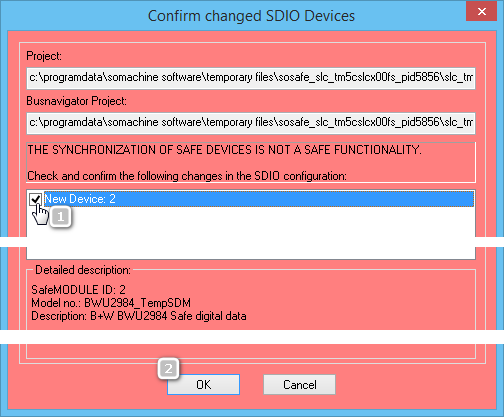
The 'Confirm changed SDIO Devices' dialog box appears.
Confirm each inserted ASi Gateway by selecting the corresponding checkbox and then confirm the dialog box with 'OK'. (See numbers (1) and (2) in the following example.)
If you reject the modifications in the device list by clicking 'Cancel', EcoStruxure Machine Expert™ – Safety is closed.
Example
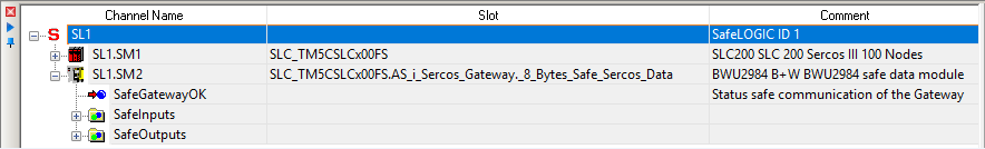
After the confirmation, the added ASi Gateways appear as Safety Logic Controller subslots in the EcoStruxure Machine Expert™ – Safety Devices tree ('Devices' window).
Example: ASi Gateway with device ID SL1.SM2
-
Parameterize the ASi Gateway device(s) as described in the following section.
How to insert the input and output bits provided by the 'x Bytes Safe Sercos Data' device object into the safety-related code (thus reading the ASi device status and writing their outputs) is described in the topic "Evaluating and Writing to ASi I/O Devices in EcoStruxure Machine Expert™ – Safety"
How to parameterize an ASi Gateway in EcoStruxure Machine Expert™ – Safety
You set up a highly distributed system which consists of an ASi application executed by the ASi Gateway, a standard (non-safety-related) LMC (PacDrive3) application, and a safety-related SLC application. Keep in mind that the extension of your safety-related application by the ASi field bus level may influence the function, performance, and overall response time of your system application. There is no superordinate, controller-spanning verification instance (or compiler) that verifies whether the various logics (Gateway, LMC, SLC) in the distributed controller application interact correctly.
The overall response time of the safety function has to be inspected and verified precisely as the integration of the ASi field bus with connected ASi devices extends the overall response time.
| WARNING | |
|---|---|
The Safety Logic Controller does not recognize the ASi I/O devices connected to the ASi field bus. It only communicates with the ASi Gateway as a Sercos subscriber. Therefore, the safety-related parameters to be set in EcoStruxure Machine Expert™ – Safety only relate to the functionality of the ASi Gateway as a Sercos bus device. The ASi I/Os cannot be parameterized in EcoStruxure Machine Expert™ – Safety.
-
In the Devices tree ('Devices' window), left-click the ASi Gateway to be parameterized. The parameters are now visible in the Device Parameterization editor on the right of the Devices tree in the 'Devices' window.
-
Set the parameters in the groups 'Basic', 'SafetyResponseTime', and 'SafetyConfiguration'. These parameters are described in the sections below.
Parameter group: Basic
Parameter: MinRequiredFWRev
|
Default value |
Basic Release |
|
Unit |
-/- |
|
Description |
This parameter is only relevant in case of implementing other firmware versions than the manufacturer-loaded version. To enter the operational state, the firmware version parameterized here or a newer version must be installed on the module. The entry 'Test Version' identifies a device firmware version which is not yet released. A safety-related application cannot get approval if devices with a firmware test version are involved. |
Parameter: Optional
|
Default value |
No |
|
Unit |
-/- |
|
Description |
The module can be configured as optional using this parameter. Optional modules do not have to be available (physically present or communicative), that is to say, if an optional module is unavailable, this is not signaled by the Safety Logic Controller. This parameter does not influence the module signal or status data. |
|
Possible values |
|
The Optional parameter is a mechanism to scale your safety-related system for various configurations of your machine design. However, it may be the case that the module(s) that you have designated as optional may be required in some of your alternate machine configurations.
| WARNING | |
|---|---|
Safety response time - general information
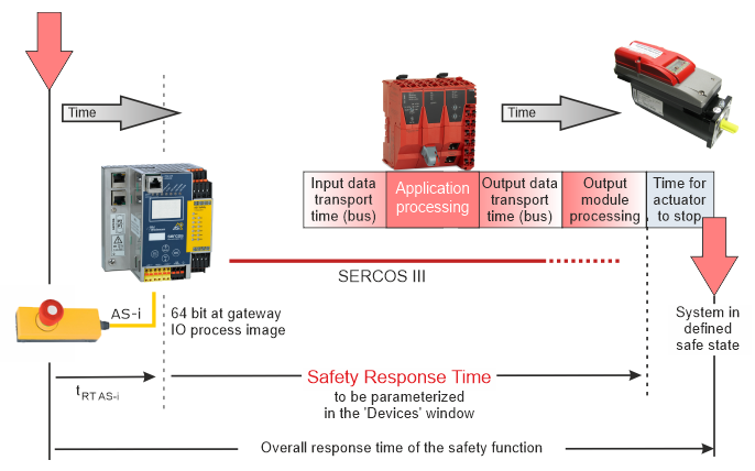
The safety response time is the time between the arrival of the sensor signal on the input channel of a safety-related input module and the shut-off signal at the output channel of a safety-related module.
The response time calculated in EcoStruxure Machine Expert™ – Safety does not include response time specific to the ASi Gateway with its connected ASi I/Os. It only considers the response time of the PacDrive 3 system until the transfer of the I/O image within the ASi Gateway.
This means that by integrating an ASi Gateway with connected ASi devices, the overall response time of the safety function is extended.
The parameters relevant for the Safety Response Time differ depending on the controller/device generation (SLCv1 and SLCv2).
Which device generation (selected in EcoStruxure Machine Expert™) you are configuring is displayed at the end of the short device description above the parameter grid (while the corresponding device is selected in the tree on the left).
Details on the Safety Response Time calculation and the difference between the SLC generations are described in the EcoStruxure Machine Expert - Safety - User Guide. There, a separate chapter is provided for each device generation:
In the 'Response Time Calculator' dialog box in EcoStruxure Machine Expert™ – Safety ('Project > Response time calculator' menu item), this is indicated as follows: after selecting an ASi Gateway (third-party device) as input or/and output module, a message appears in the dialog box informing you that the response times of the ASi Gateway and the connected ASi devices have to be added manually to the calculated response time in order to determine the overall response time of the safety function.
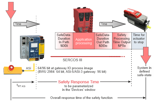
This ASi specific response time is referred to as tRT ASi in the following figure. tRT ASi must include the ASi bus cycle time, transfer times between Sercos and ASi bus, processing time in sensor, and application processing in ASi Gateway (depending on your application).
Refer to the documentation provided by Bihl+Wiedemann for details regarding the calculation and determination of ASi specific response times.
Safety response time for a safety-related system with an SLCv1 generation device
Safety response time for a safety-related system with an SLCv2 generation device
| WARNING | |
|---|---|
Parameter group: SafetyResponseTime (only valid with SLCv1)
This section applies to a safety-related system with an SLCv1 generation device (SLC100 or SLC200). Which device generation is configured in your project is visible at the end of the short device description above the parameter grid (while the device is selected in the tree on the left).
The parameters in this group influence the safety response time of the Safety Logic Controller system.
The parameters CommunicationWatchdog, MinDataTransportTime, and MaxDataTransportTime in this group are only applied to the module if ManualConfiguration is set to 'Yes'.
Parameter: ManualConfiguration
|
Default value |
No |
|
Unit |
-/- |
|
Description |
Specifies whether the module uses its safety response time-relevant parameters (CommunicationWatchdog, MinDataTransportTime, and MaxDataTransportTime) or the values specified in the 'SafetyResponseTimeDefaults' parameter group of the Safety Logic Controller. Managing parameters per module can optimize the system to application-specific requirements regarding the safety response time. |
|
Parameter value |
|
Parameter: MinDataTransportTime
|
Default value |
12 |
|
Unit |
100 µs |
|
Description |
Defines the minimum time that is required to transmit a data telegram from a producer to a consumer. If a telegram is received earlier (by the consumer) than specified by this parameter value, communication is considered as invalid. EcoStruxure Machine Expert™ – Safety provides a calculator dialog box to determine this parameter value. Term definition and background information According to the openSAFETY specification, devices (safety-related I/O modules as well as the Safety Logic Controller) communicate by sending and receiving cyclic data, referred to as openSAFETY telegrams. A telegram generating (sending) device is designated as producer, a receiving device is a consumer. Each telegram includes a time stamp for time validation of the communication. On receipt of a telegram, the consumer compares this time stamp with the current time. If the schedule is kept, the communication is considered as valid. If a telegram is received earlier than defined by this parameter, communication is considered as invalid and is not further processed. The 'SafeModuleOK' process data item also becomes SAFEFALSE indicating that the safety-related communication of the module is no longer valid. The implications for the rest of the safety-related systems depend on the defined safety-related function. |
|
Value calculation |
How to calculate the module-specific MinDataTransportTime value
|
|
Practical values |
Entering the MinDataTransportTime value calculated in EcoStruxure Machine Expert™ – Safety helps building a stable running system. Permissible value range: 12-500 |
Parameter: MaxDataTransportTime
|
Default value |
250 |
|
Unit |
100 µs |
|
Description |
Defines the maximum time that is allowed to transmit a data telegram from a producer to a consumer. If a telegram is received later (by the consumer) than specified by this parameter value, communication is considered as invalid. EcoStruxure Machine Expert™ – Safety provides a calculator dialog box to determine this parameter value.
NOTE:
The parameter value influences the safety response time calculated by EcoStruxure Machine Expert™ – Safety. Term definition and background information According to the openSAFETY specification, devices (safety-related I/O modules as well as the Safety Logic Controller) communicate by sending and receiving cyclic data, referred to as openSAFETY telegrams. A telegram generating (sending) device is designated as producer, a receiving device is a consumer. Each telegram includes a time stamp for time validation of the communication. On receipt of a telegram, the consumer compares this time stamp with the current time. If the schedule is kept, the communication is considered as valid. If a telegram is received later than defined by this parameter, communication is considered as invalid and is not further processed. The implications for the rest of the safety-related systems depend on the defined safety-related function. |
|
Value calculation |
How to calculate the module-specific MaxDataTransportTime value
|
|
Practical values |
Entering the MaxDataTransportTime value calculated in EcoStruxure Machine Expert™ – Safety helps building a stable running system. Permissible value range: 12-65,000 |
Parameter: CommunicationWatchdog
|
Default value |
200 |
|
Unit |
100 µs |
|
Description |
Defines the maximum time period within which a consumer must receive a valid data telegram from a producer in order to consider the safety-related communication as valid and continue the application. The parameter sets a watchdog timer which then monitors whether a consumer receives telegrams from a producer in time. If the watchdog expires, communication is considered as invalid. EcoStruxure Machine Expert™ – Safety provides a calculator to determine this parameter value.
NOTE:
The parameter value influences the safety response time calculated by EcoStruxure Machine Expert™ – Safety. Term definition and background information According to the openSAFETY specification, devices (safety-related I/O modules as well as the Safety Logic Controller) communicate by sending and receiving cyclic data, referred to as openSAFETY telegrams. A telegram generating (sending) device is designated as producer, a receiving device is a consumer. The CommunicationWatchdog value physically depends on the transport time needed for the telegram to be transmitted from a producer to a consumer and is used in the calculation of the worst case response time of the system. The calculated parameter value therefore depends on the MaxDataTransportTime parameter value. If the consumer receives the telegram in time (communication watchdog is not expired and the transmission time is within the period specified by the parameters MinDataTransportTime and MaxDataTransportTime), the watchdog timer is restarted and communication is considered as valid. The time stamp contained in the received telegram is not evaluated, only the receipt of a valid telegram is relevant. If no telegram is received (due to delay or loss) and the communication watchdog expires in the consumer, the module is set to the defined safe state. The 'SafeModuleOK' process data item also becomes SAFEFALSE indicating that the safety-related communication of the module is no longer valid. |
|
Value calculation |
How to calculate the module-specific CommunicationWatchdog value
|
|
Practical values |
For the CommunicationWatchdog value which you have to enter in the parameter grid ('Devices' window), the following applies:
Permissible value range: 1-65,535 |
Parameter group: SafetyResponseTime (only valid with SLCv2)
This section applies to a safety-related system with an SLCv2 generation device (SLC300 or SLC400). Which device generation is configured in your project is visible at the end of the short device description above the parameter grid (while the device is selected in the tree on the left).
The parameters in this group influence the safety response time of the Safety Logic Controller system. The parameters SafeDataDuration and ToleratedPacketLoss in this group are only applied to the module if ManualConfiguration is set to 'Yes'.
Parameter: ManualConfiguration
|
Default value |
No |
|
Unit |
-/- |
|
Description |
Specifies whether the module uses its safety response time-relevant parameters (SafeDataDuration and ToleratedPacketLoss) or the values specified in the 'SafetyResponseTimeDefaults' parameter group of the Safety Logic Controller. Managing parameters per module can optimize the system to application-specific requirements regarding the safety response time. |
|
Parameter value |
|
Parameter: SafeDataDuration
|
Default value |
200 |
|
Value range Step size |
25...9,380 1 |
|
Unit |
100 µs |
|
Description |
This parameter influences the safety response time of the safety-related application. Specifies the maximum permissible time for data transmission from a safety-related producer to a consumer, that is to say, from an input module to the SLC, or from the SLC to an output module. Based on this parameter value and the value of the 'ToleratedPacketLoss' parameter (described below), and further module-specific processing times, the Safety Response Time (SRT) is calculated. Verify the SRT resulting from the parameter values entered here using the 'Response Time Calculator' dialog box in EcoStruxure Machine Expert™ – Safety (menu item 'Project > Response Time Calculator'). |
|
Value calculation |
The risk analysis you have performed for your safety-related application delivers the maximum allowed overall response time of the safety function and, as part of this, the safety function response time (SRT) of the signal chain. The SRT for the ASi Gateway is composed of the following time values:
with
(including configured delay times),
This allowed SRT value is the basis for the calculation of the SafeDataDuration (SDD) and the ToleratedPacketLoss (TPL) value you must enter as the parameter value in the grid. From the allowed SRT, deduct the processing time of the safety-related output module (SPTo). The result is the total maximum permissible time for the safety-related data transmission on the complete safety-related path, that is to say, from the ASi Gateway to the output module. As the SafeDataDuration parameter relates to only one transmission path (ASi Gateway -> SLC or SLC -> output module), you must divide the value by 2 to get the required value to be entered in the parameter grid. If a packet loss is tolerated, this must also be considered. The calculation equation is as follows:
|
Parameter: ToleratedPacketLoss
|
Default value |
1 |
|
Value range Step size |
0...10 1 |
|
Unit |
Data packets |
|
Description |
Specifies the maximum allowed number of lost packets during data transmission. The number of tolerated packet losses affects the safety response time. Based on this parameter value and the value of the 'SafeDataDuration' parameter, the Safety Response Time (SRT) of the system is calculated. Verify the SRT resulting from the parameter values entered here using the 'Response Time Calculator' dialog box in EcoStruxure Machine Expert™ – Safety (menu item 'Project > Response Time Calculator'). |
Parameter group: SafetyConfiguration
Parameter: ConfigID
Each ASi application is verified by a unique checksum which is generated in ASIMON360 before copying the configuration data to the ASi Gateway and commissioning the ASi application. In ASIMON360, this checksum is called ConfigID.
The checksum is used in EcoStruxure Machine Expert™ – Safety for verifying that the configuration loaded in the ASi Gateway is valid and corresponds to the ASi configuration entered in EcoStruxure Machine Expert™ – Safety.
Each modification in the ASi application results in a newly calculated unique ConfigID. After a modification of the ASi application, and consequently entering the new ConfigID value in EcoStruxure Machine Expert™ – Safety, and rebuilding the safety-related SLC application, also the 'Project CRC' of the SLC application is modified. (The 'Project CRC' is indicated in the 'Project Info' dialog box in EcoStruxure Machine Expert™ – Safety.) Note that a changed 'Project CRC' implies a new acceptance procedure for the entire safety-related project.
Read the ConfigID checksum from the ASIMON360 configuration tool and enter it as ConfigID value in the parameterization editor.
You can also display the ConfigID at the ASi Gateway device. Press the 'OK' button at the device to enter the menu and select 'Safety > Safe Sercos > Config IDs (Node and Manager)' to display the ConfigID.
-
The 'Node' entry on the displayed screen outputs the ConfigID configured on the ASi Gateway device.
-
The 'Manager' entry displays the ConfigID which is entered in the safety-related device ASi Gateway parameters in EcoStruxure Machine Expert™ – Safety.
NOTE:If the value is 0 or an incorrect ConfigID, either no communication connection is established between EcoStruxure Machine Expert™ – Safety and the ASi Gateway, or communications will be unsuccessful because of the invalid ConfigID.
By entering the checksum in EcoStruxure Machine Expert™ – Safety, you confirm that you know and consider the mapping of safety-related data to the 'x Bytes Safe Sercos Data' device object in the ASi application (with x = 8 for the BWU2984 and x = 12 for the ASi-5/ASi-3 Gateway).
| WARNING | |
|---|---|
Also refer to section "ConfigID by B+W corresponds to safety-related ConfigID parameter".