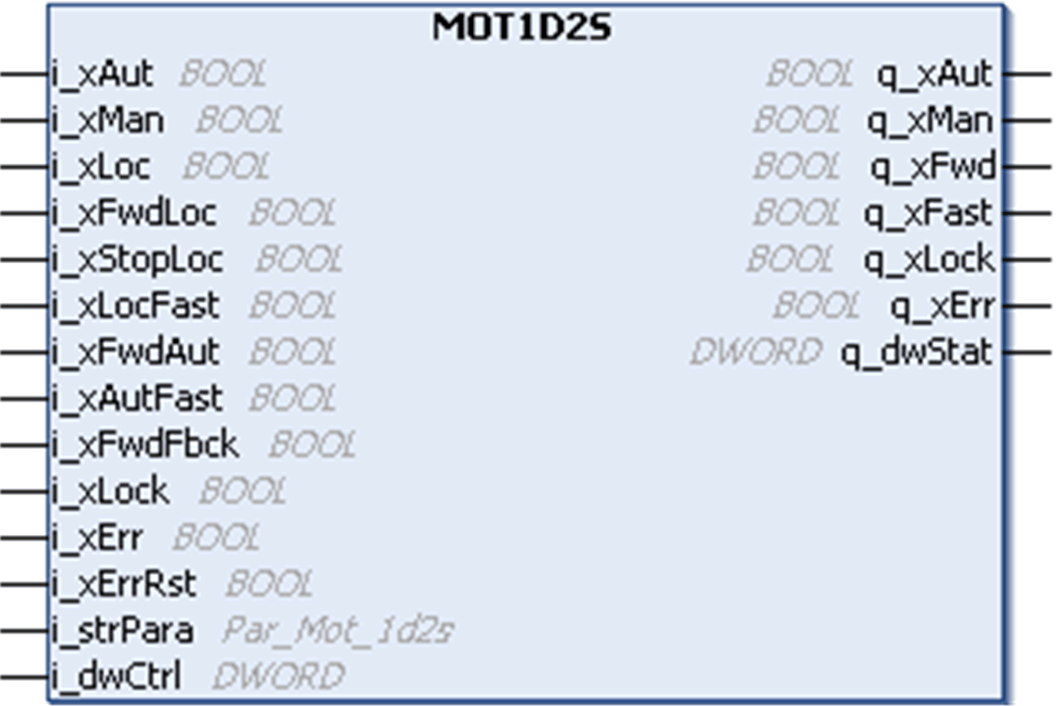
The MOT1D2S generic function block is dedicated to the control and command of motors with one direction of rotation and two speeds through any actuator connected in parallel through digital I/Os or through communication networks like Modbus Serial Line or CANopen.
The motor can be controlled through 3 different operating modes : automatic, manual using push-buttons, or manual using HMI.
This figure shows the pin diagram of the MOT1D2S function block:

The MOT1D2S function block supports three modes of operation:
oAutomatic Mode: The automatic mode is selected through the input pin i_xAut. In automatic mode, the motor is started and stopped through the input pin i_xFwdAut, regardless of the activation of local mode. The output q_xFwd remains high, as long as the input i_xFwdAut remains high, and there is no detected error or interlock. The i_xAutFast input allows to activate fast speed. These inputs are controlled by the controller process application during normal functioning.
oManual Mode: The manual mode is activated by the pin i_xMan.
Case 1: Local mode is not activated. The motor is started and stopped through the bit commands of the signal i_dwCtrl. This double word can be associated to an external HMI equiped with a keypad.
Case 2: Local mode is activated through the input pin i_xLoc. The motor is started and stopped through the input signals i_xFwdLoc and i_xLocStop. These digital inputs can be linked to connect push-buttons.
oLocal Mode: The local mode is activated by an input pin i_xLoc, and is set additionally to the automatic or manual mode. The local mode does not influence the automatic mode, but changes the source for manual operation.
The block is de-activated on controller start and remains in the same operation mode, unless a new one is selected. If both automatic and manual modes are selected simultaneously (inputs i_xAut and i_xMan are set to 1), the operation mode is invalid which is indicated at the q_xErr output.
|
|
|
UNINTENDED MOTOR STOP |
|
Do not change from manual mode to automatic mode when the motor is being used, doing so will make the motor stop. |
|
Failure to follow these instructions can result in injury or equipment damage. |
To enable the fast speed in the automatic mode, the input i_xAutFast should be set to 1. The bit command of the signal i_dwCtrl must be set in the manual mode or i_xLocFast must be set, if the control is switched to local mode.
The operation of the motor is supervised by feedback signal (i_xFwdFbck), which indicates the running motor. The feedback signal must adjust its value to the value of the related output q_xFwd within a defined time. If the time is exceeded, the block indicates a detected error (Missing Feedback detected error). The time can be set via the structure element iFbckDly at input i_strPara. The supervision can be switched off by the structure element xEnFb at the input i_strPara.
The motor can run, only if the interlock input i_xLock is set to 0. An active interlock signal inhibits the start/stop of the motor. When the interlock signal returns to 0 the motor is restarted. An active interlock is indicated at the output q_xLock.
The motor can run only if the output q_xErr is set to 0. An active detected error signal inhibits the start or stop of the motor. The function block sets the detected error signal, if the detected error input i_xErr is set to 1 (external detected error) or in case of an invalid operation mode or a missing feedback signal (internal detected errors).
The single detected errors are indicated in the HMI as alarms. To reset the detected error output, the detected error has to be acknowledged by a rising edge on the input i_xAckn or by using the 16th bit of the signal i_dwCtrl.