Interface for Hall Effect Sensors
Overview
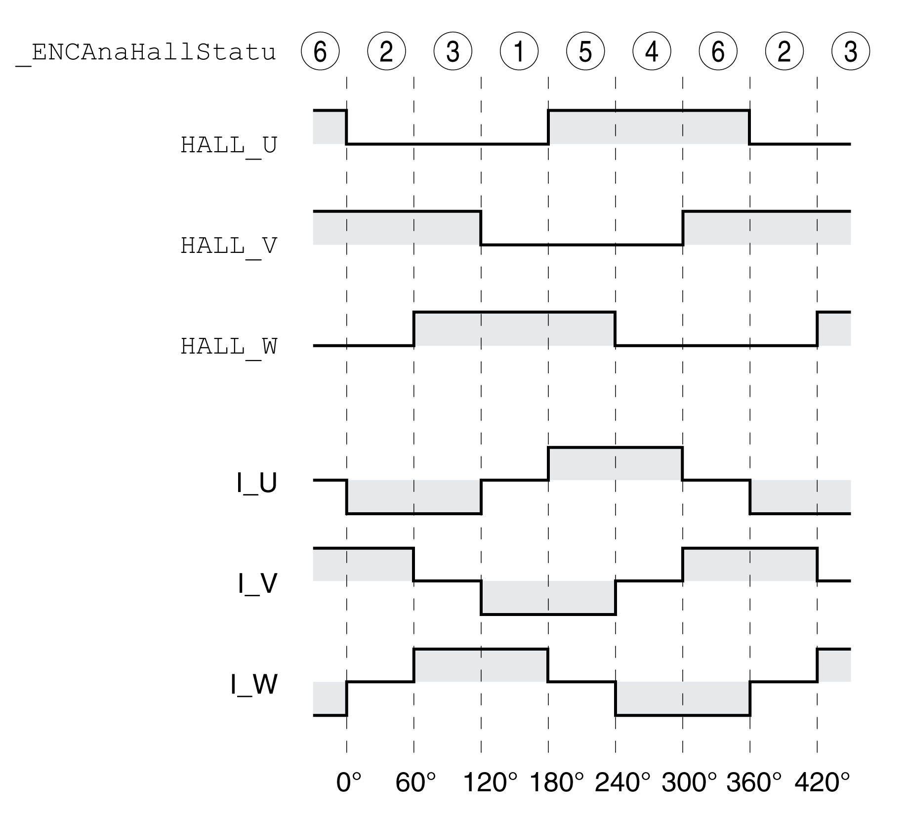
The sequence of the Hall effect sensor signals must correspond to the pattern 2 - 3 - 1 - 5 - 4 - 6 as indicated in the following illustration.

The encoders of third-party motors may deliver a different pattern even though the designations HALL_U, HALL_V and HALL_W are used. In such a case, the encoder pins HALL_U, HALL_V and HALL_W must be wired differently.
Verification of the Sequence
Observe and note the values of the parameter _ENCAnaHallStatu in the commissioning software for one rotation of the motor shaft in positive direction of movement. Positive direction of rotation is when the motor shaft rotates clockwise as you look at the end of the protruding motor shaft.
The noted sequence must correspond to the pattern 2 - 3 - 1 - 5 - 4 - 6.
|
Parameter name HMI menu HMI name |
Description |
Unit Minimum value Factory setting Maximum value |
Data type R/W Persistent Expert |
Parameter address via fieldbus |
|---|---|---|---|---|
|
Sequence of Hall effect sensor signals of analog encoder. This parameter can be used to read the sequence of the Hall effect sensor signals of an analog encoder with the interface "SinCos 1Vpp (with Hall)". Type: Unsigned decimal - 2 bytes |
- 0 - 7 |
UINT16 R/- - - |
Modbus 20742 IDN P-0-3081.0.3 |
If the sequence noted is different, adapt the wiring of the Hall effect sensor:
-
For sequence 4 - 5 - 1 - 3 - 2 - 6: interchange the Hall effect signals HALL_U with HALL_V.
-
For sequence 1 - 3 - 2 - 6 - 4 - 5: interchange the Hall effect signals HALL_V with HALL_W.
-
For sequence 4 - 6 - 2 - 3 - 1 - 5: interchange the Hall effect signals HALL_U with HALL_W, HALL_V with HALL_U and HALL_W with HALL_V.