The use of sensors can provide some protection against hazards (for example, collision with mechanical stop caused by incorrect reference values).
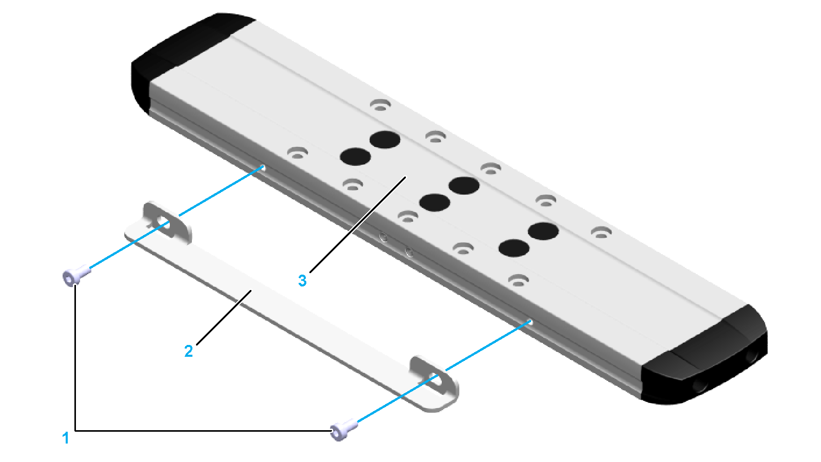
For the functionality of the inductive sensors, a contact plate must be mounted to the carriage. Fastening threads are located at both sides of the carriage.
|
|
|
LOSS OF CONTROL |
|
oEnsure that sensors are installed if your application, based on your risk assessment, requires sensors. oVerify correct connection of the sensors. oVerify that the sensors are sufficiently distant from the mechanical stop to allow an adequate stopping distance. oVerify correct parameterization and function of the sensors. |
|
Failure to follow these instructions can result in death, serious injury, or equipment damage. |
NOTE: If possible, use normally closed contacts as sensors so that a wire break can be signaled as an error.
Fastening Material for Sensor Mounting
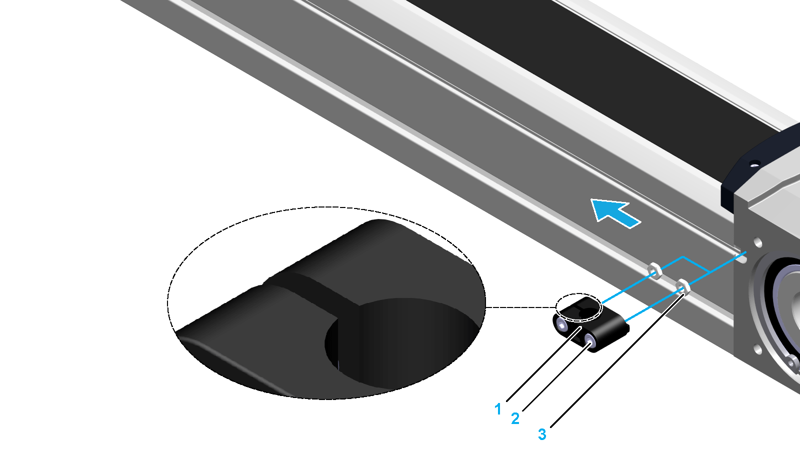
A sensor is mounted to the axis body by using a sensor holder. The axis body provides a T-slot for the sensor holder. This T-slot has cutouts at both end blocks for inserting the fastening nuts. In addition, the sensor holder has cams at both sides to keep the sensor from turning in the T-slot.
The following graphic presents the components of a sensor holder:

1 Fastening nuts*
2 Sensor holder
3 Hex socket screw
* For fastening the sensor in the sensor holder and the sensor holder in the T-Slot.
You need the following tools to mount the sensors:
oFeeler gauge
oTorque wrench with hexagon socket
For suitable parts, refer to Replacement Equipment and Accessories.
Perform the following procedures for each sensor to be replaced:
oPreparing the mounting of the sensor
oMounting the sensor to the sensor holder
Preparing the Mounting of the Sensor
|
Step |
Action |
|---|---|
|
1 |
Verify the sensor for correct type and function. |
|
2 |
Verify that your controller and your interface are suitable for the sensor. |
|
3 |
Clean all parts. |
|
4 |
Inspect all parts for damage. |
|
NOTICE |
|
UNINTENDED EQUIPMENT OPERATION |
|
oReplace any damaged parts immediately. oClean all parts before assembly and use. |
|
Failure to follow these instructions can result in equipment damage. |
|
Step |
Action |
|---|---|
|
1 |
Fasten the contact plate (2) to the carriage (3) with the two screws (1). Use the standard tightening torque. NOTE: oAlign the contact plate level with the carriage to have the same switching distance on both sides. oMount the contact plate to the side of the carriage that is easily accessible for service. 
|
|
Step |
Action |
|---|---|
|
1 |
Slide each nut (3) into the T-slot at the cutout. 
NOTE: The slot of the sensor holder should point to the carriage. |
|
2 |
Position the sensor holder (1) with the two screws at the nuts. Leave the two screws loose. |
|
3 |
Slide the senor holder to the sensor position and tighten screw (2). For further information, refer to the dimensional drawing of the respective axis in Mechanical Data. Tightening torque: 0.3 Nm (2.66 lbf-in). |
Mounting the Sensor to the Sensor Holder
Before you mount the sensor, be aware of the switching distance:
NOTE: Since the sensor operates inductively, the switching surface must have a specific distance from the contact plate. This switching distance is 0.5 +/- 0.1 mm (0.00197 +/- 0.00039 in).
|
Step |
Action |
|---|---|
|
1 |
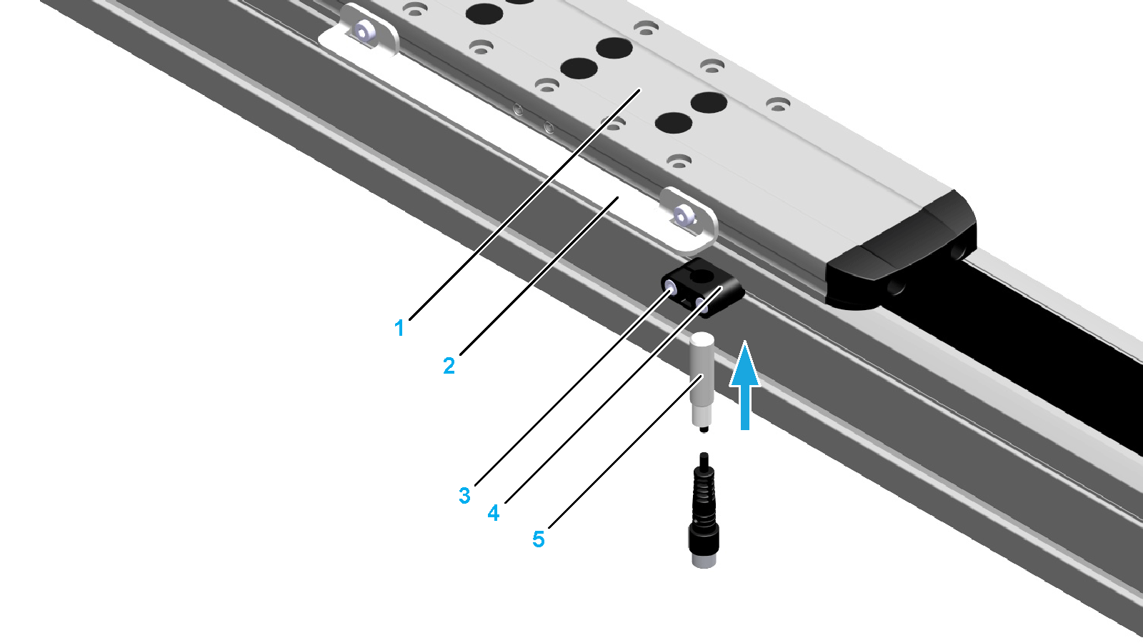
Move the carriage (1) until the contact plate (2) is above the sensor holder (4). 
|
|
2 |
Slide the sensor (5) through the sensor holder opening until the switching distance s is obtained. Use a feeler gauge to measure the switching distance. |
|
3 |
Tighten screw (3) to fix the sensor. Tightening torque: 0.3 Nm (2.66 lbf-in). |
|
4 |
Verify the correct switching distance with the feeler gauge. |
|
5 |
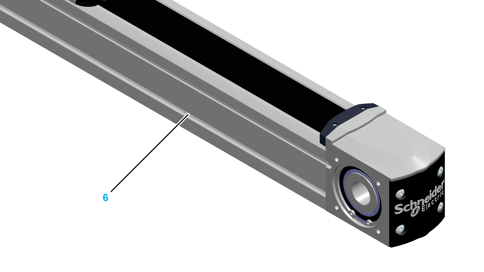
Route the sensor cable in the T-slot (6). 
NOTE: oThe T-slot can hold up to three sensor cables. For suitable parts, refer to Replacement Equipment and Accessories. oIf the lateral T-slots are used for the installation of the axis, the sensor cable cannot be completely routed in the T-slots. |