Replacing the toothed belt can cause unanticipated movements.
|
|
|
UNINTENDED MOVEMENTS DUE TO DISMOUNTING |
|
Secure the moving parts of the axes mounted in a vertical or tilted position against unexpected movements. |
|
Failure to follow these instructions can result in death, serious injury, or equipment damage. |
You need the following tools to remove the toothed belt:
oSet of hex keys
oMedium strength threadlocker
oTorque wrench with a set of hexagon sockets
NOTE: Do not use ball head hex keys. Excessive torque may cause the ball head to break away. A broken ball head makes the removal of the screw difficult.
To adjust the toothed belt tension, you need a:
oCaliper gauge (for distance measurement) or
oBelt tension meter (for vibration measurement)
For suitable parts, refer to Replacement Equipment and Accessories.
Distance and Vibration Measurement
For adjusting the toothed belt tension, you can use either distance measurement or vibration measurement:
oDistance measurement
The position of the toothed belt tensioner is measured with a caliper gauge. The position of the toothed belt tensioner is used to preload the toothed belt.
oVibration measurement
To restore the precise factory-adjusted toothed belt tension, use a belt tension meter for vibration measurement. The factory-adjusted toothed belt tension is presented in the following table. The measured preload values FV depend on the selectable measuring distance A and the weight of the respective toothed belt.
The measuring distance A is measured:
oFrom the center of the end block
oTo the edge of the carriage

|
Description |
Parameter |
Unit |
Value |
|||
|---|---|---|---|---|---|---|
|
PAS41 |
PAS42 |
PAS43 |
PAS44 |
|||
|
Toothed belt type |
– |
– |
HTD3 |
HTD5 |
HTD5 |
HTD8 |
|
Width |
– |
mm (in) |
15 (0.59) |
25 (0.98) |
30 (1.18) |
50 (1.97) |
|
Pitch |
– |
3 (0.118) |
5 (0.197) |
5 (0.197) |
8 (0.315) |
|
|
Weight |
– |
g/m (lb/ft) |
32 (0.0215) |
96 (0.065) |
118 (0.08) |
311 (0.21) |
|
Toothed belt tension |
Fv |
N (lbf) |
145…180 (32.6…40.5) |
570…710 (128…160) |
670…840 (151…189) |
1915…2400 (431…540) |
For any questions concerning the vibration measurement, contact your your local Schneider Electric service representative.
Perform the following procedures to replace the toothed belt:
oPreparing the replacement of the toothed belt
oCutting the new toothed belt into length
Preparing the Replacement of the Toothed Belt
|
Step |
Action |
|---|---|
|
1 |
Remove or support the payload and the carriage if the axis is tilted or mounted vertically. |
|
2 |
If installed, remove the cover strip as described in Replacing the Cover Strip. |
To remove the toothed belt, perform the tasks described below at both ends of the carriage and at both end blocks.
NOTE: If you have already removed the rubber buffers and the strip deflectors due to removing the cover strip, proceed with step 5.
|
Step |
Action |
|---|---|
|
1 |
Remove the two screws (3) at the rubber buffer (2). 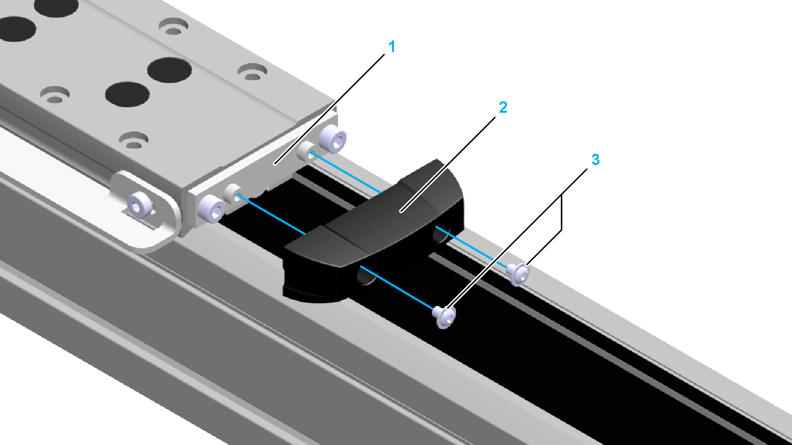
|
|
2 |
Remove the rubber buffer from the holding plate (1). |
|
3 |
Remove the two screws (4) and the holding plate from the carriage. 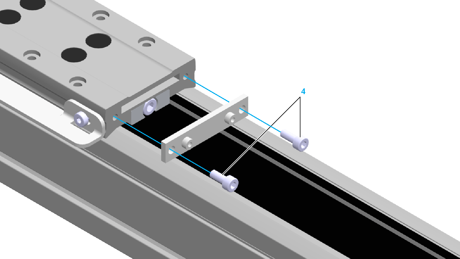
|
|
4 |
When using distance measurement, perform the following step: Measure the position of the toothed belt tensioner (5) with a caliper gauge at both sides of the carriage and note the values. The distance e has to be measured from the front side of the toothed belt tensioner to the front side of the carriage. 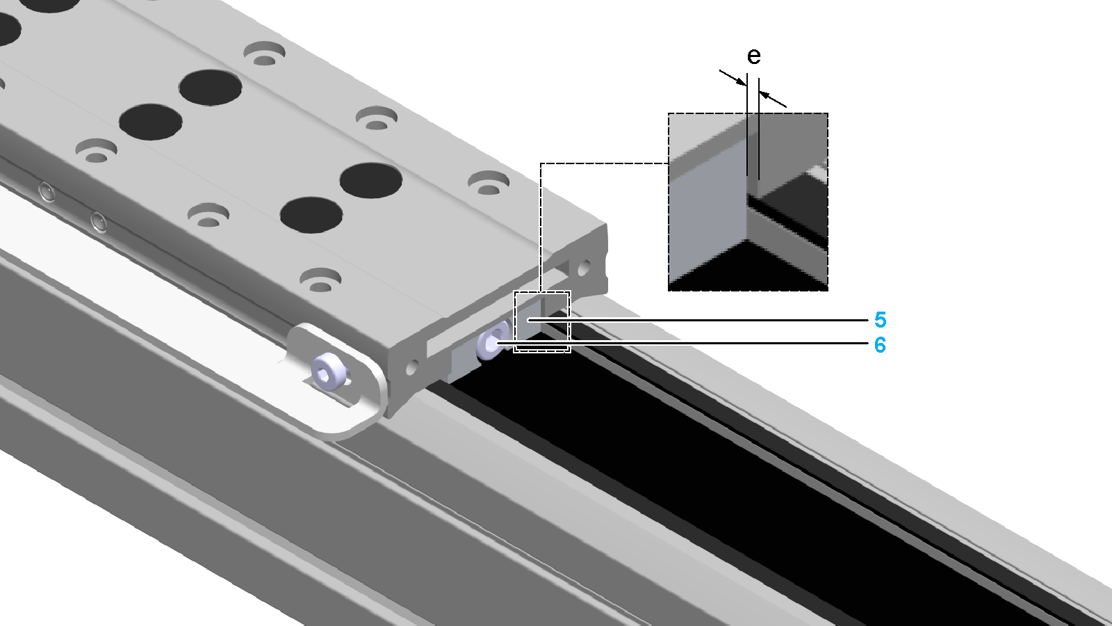
|
|
5 |
Remove the tensioning screw (6) at the toothed belt tensioner. |
|
6 |
Pull out the toothed belt tensioner along with the toothed belt (8). NOTE: This may require a considerable force. 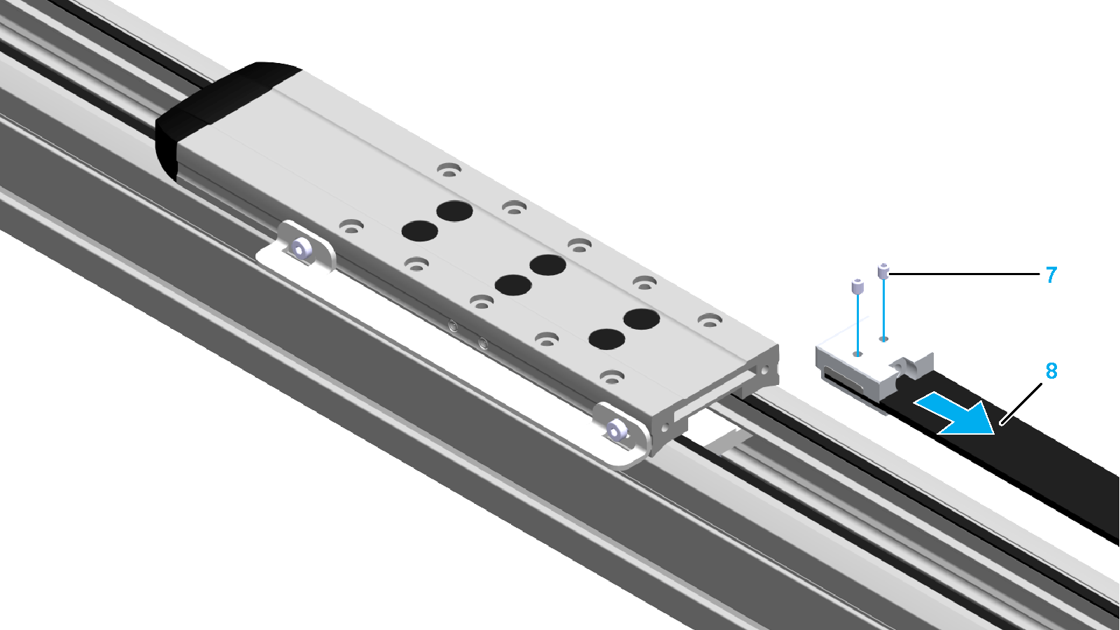
|
|
7 |
Loosen the two setscrews (7) at the toothed belt tensioner. NOTE: This requires a considerable force due to the threadlocker. |
|
8 |
Slide the toothed belt and the clamping plate (9) to the side out of the toothed belt tensioner. 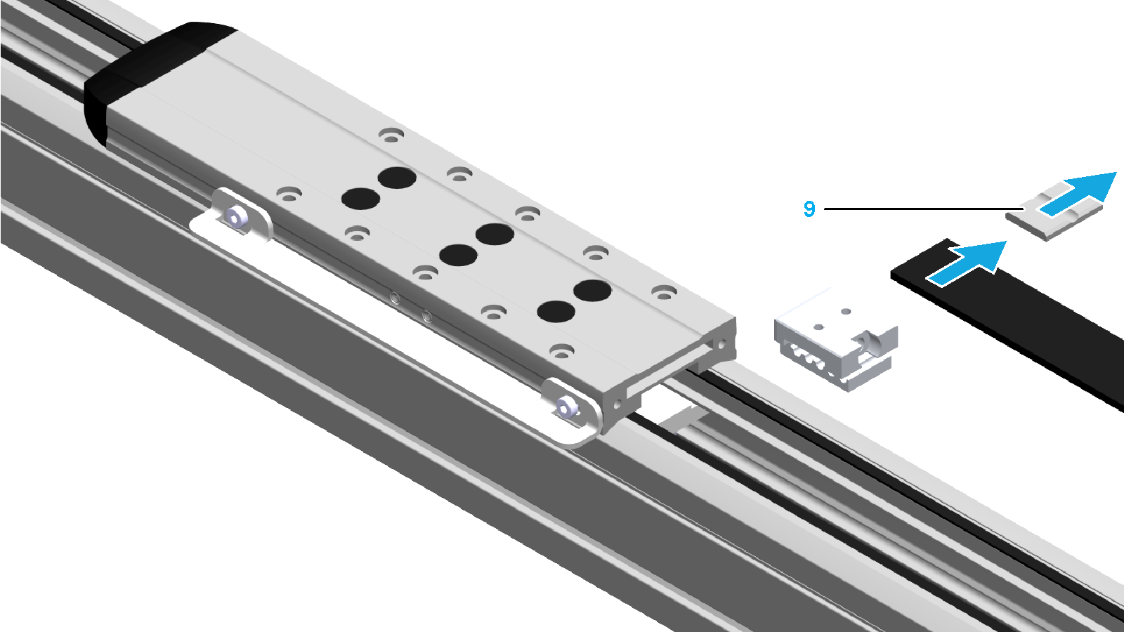
|
|
9 |
Remove the four screws at the cover of the end block (10). 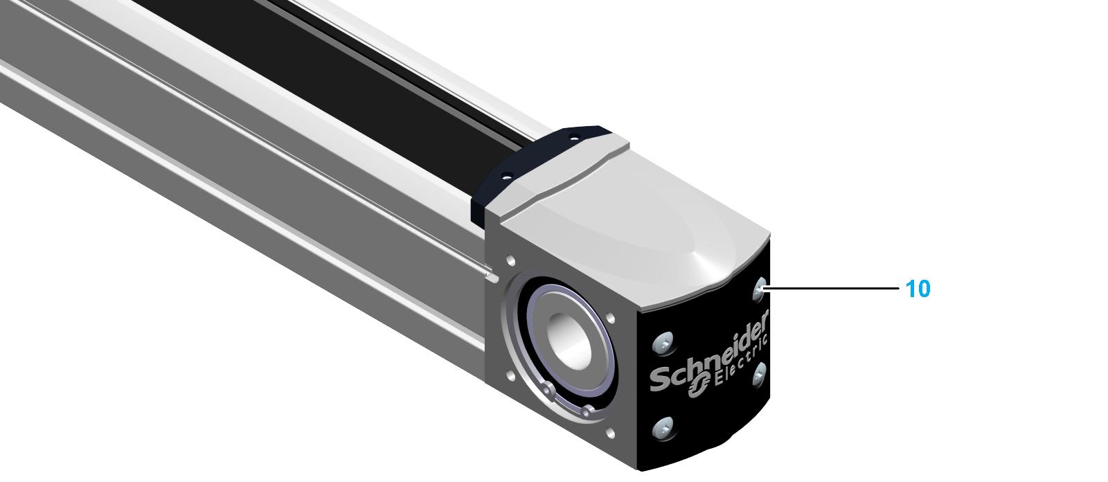
|
|
10 |
Remove the cover. |
|
11 |
Remove the toothed belt. 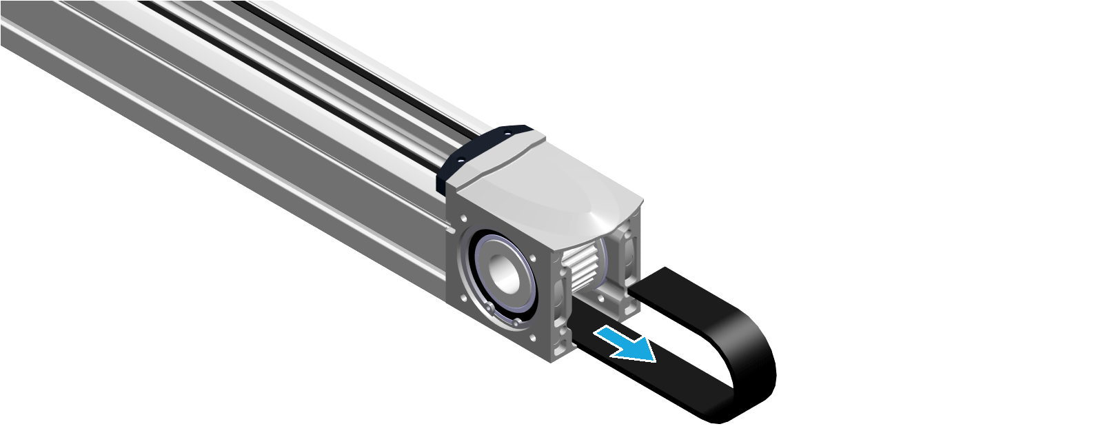
|
Cutting the New Toothed Belt to Length
|
Step |
Action |
|---|---|
|
1 |
Place the new toothed belt (1) and the previous toothed belt (2) next to each other. Align the teeth with each other. 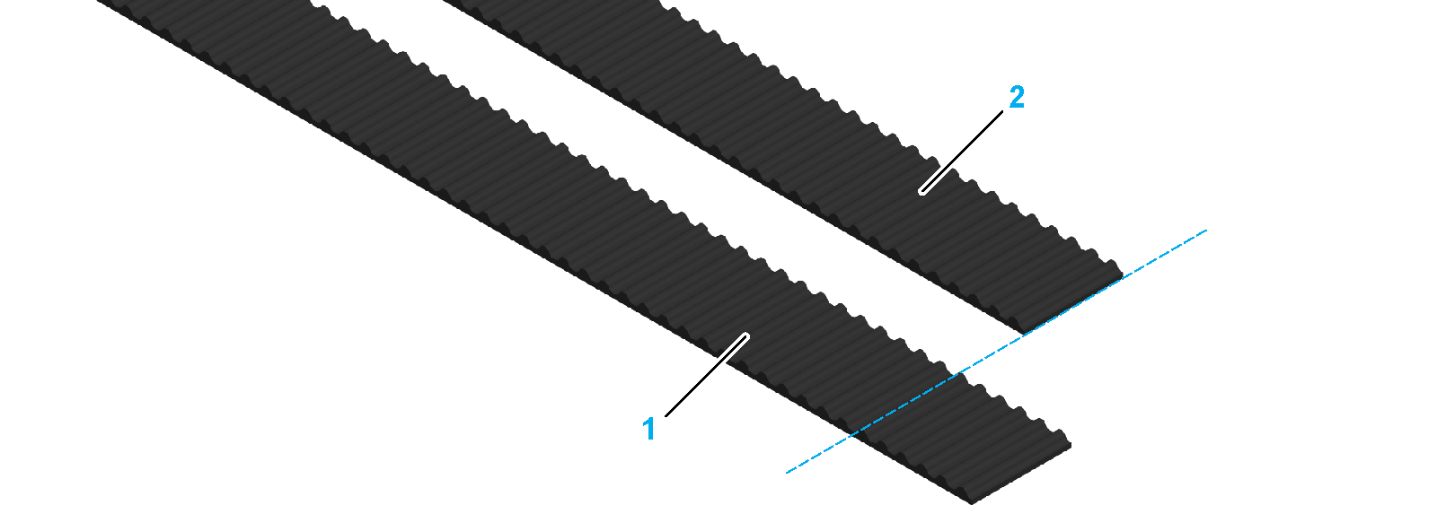
|
|
2 |
Cut the new toothed belt to the same length as the previous toothed belt. 
NOTE: The number of teeth must be the same. |
|
Step |
Action |
|---|---|
|
1 |
Insert one end of the new toothed belt with up-pointing teeth (3) into an end block below the toothed belt pulley (2). Slide the toothed belt through the axis body (1) until the toothed belt comes out on the other end of the axis. 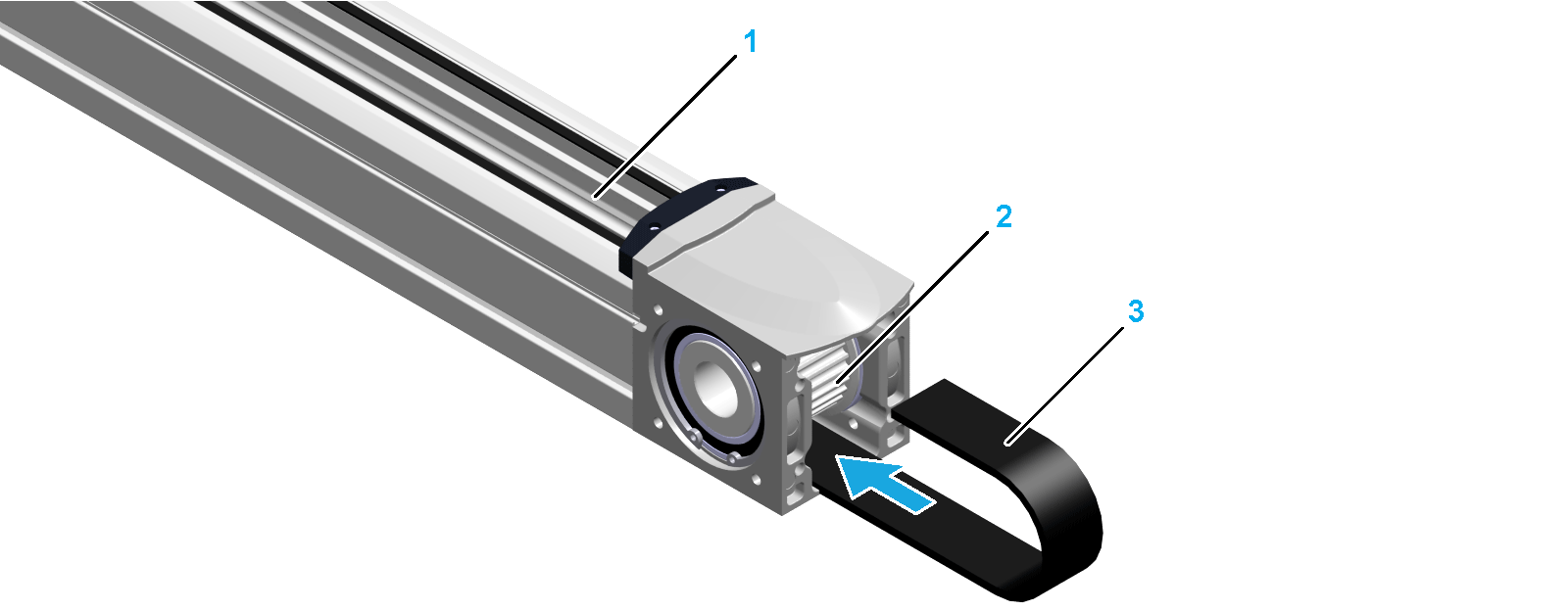
|
|
2 |
Insert the other end of the toothed belt into the end block above the toothed belt pulley. 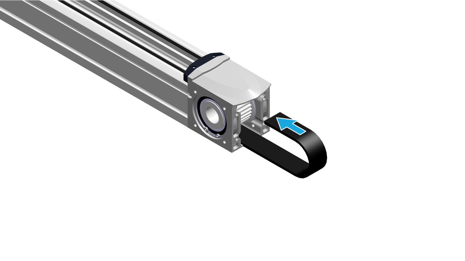
|
|
3 |
Insert the end of the toothed belt from the side into the toothed belt tensioner (5) so that all five teeth are covered. 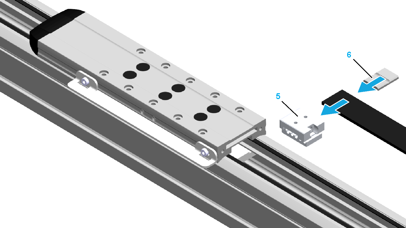
|
|
4 |
Insert the clamping plate (6) with the recess pointing upward from the side into the toothed belt tensioner. NOTE: Verify that the toothed belt is inserted symmetrically and the clamping plate is inserted flush into the toothed belt tensioner. |
|
5 |
Apply a thin layer of medium strength threadlocker to the setscrews (7) at the toothed belt tensioner (8) and tighten the setscrews. Tightening torque: oFor PAS41: 0.1 Nm (0.0039 lbf-in) oFor PAS42: 0.15 Nm (0.0059 lbf-in) oFor PAS43: 0.15 Nm (0.0059 lbf-in) oFor PAS44: 0.3 Nm (0.018 lbf-in) 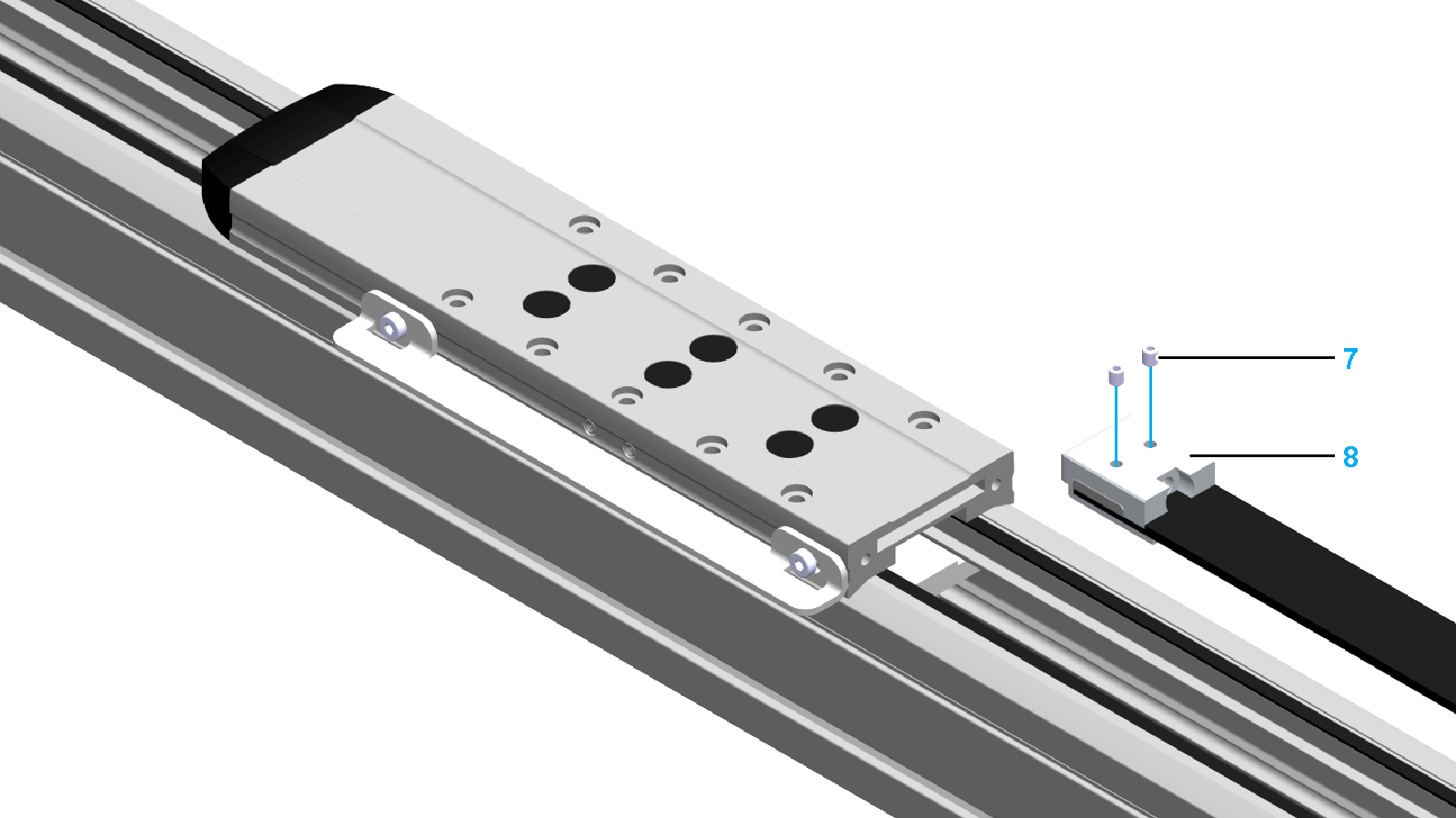
|
|
6 |
Insert the toothed belt tensioner with the mounted toothed belt into the carriage (9). 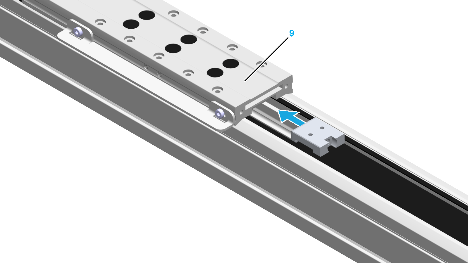
|
|
7 |
Tension the toothed belt by adjusting the tensioning screws (10) at both ends of the carriage. Use either distance or vibration measurement: oWith distance measurement: tension the tensioning screw with the values noted in Removing the Toothed Belt. oWith vibration measurement: tension the tensioning screw until the respective toothed belt tension is reached. 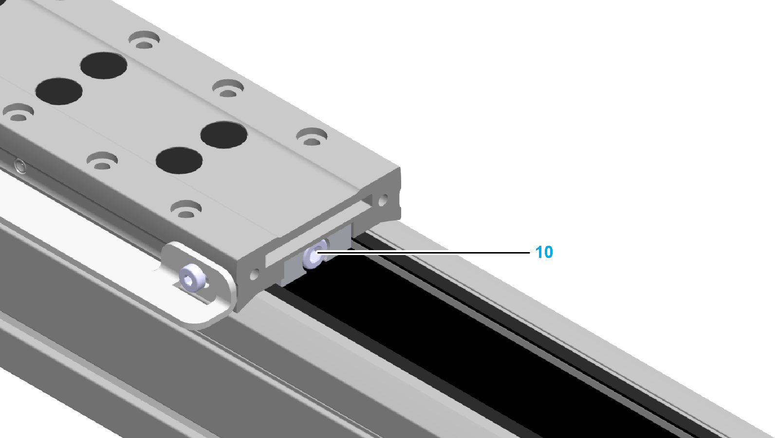
|
|
8 |
If applicable, mount the strip deflectors and the cover strip. For further information, refer to Mounting the Cover Strip. |
|
9 |
Fasten the holding plate (11) to the carriage with the two screws (12). Verify that there is no clearance between the holding plate and the carriage such that the surfaces are flush. 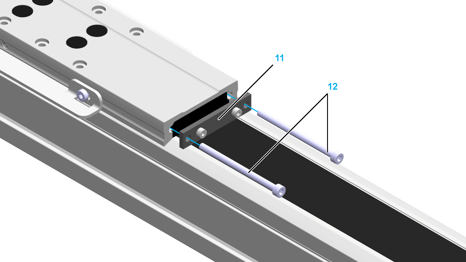
|
|
10 |
Fasten the rubber buffer (13) to the holding plate with the two screws (14). Verify that there is no clearance between the rubber buffer and the holding plate such that the surfaces are flush. 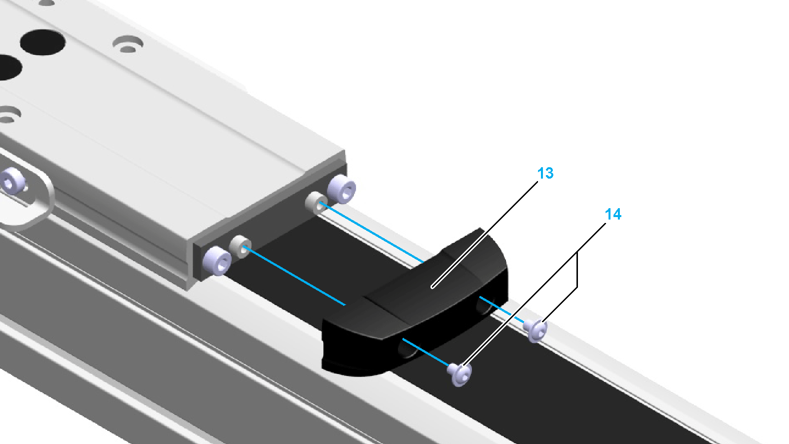
|
|
Step |
Action |
|---|---|
|
1 |
Run initial tests at reduced velocity. |
|
2 |
Verify the toothed belt tension. For details, refer to Maintaining the Toothed Belt. |
|
3 |
Mount the payload. |