The pulse width modulation function generates a programmable pulse wave signal on a dedicated output with adjustable duty cycle and frequency.
NOTE: Enable the functionality either by setting F_Enable to 1, or by an external event with the IN_EN input and EN_Enable=1, otherwise the output (OUT_PWM) stays to 0.
The PTO and PWM, and frequency generator functions use the same dedicated outputs. Only one out of these 3 functions can be used on the same channel. Using different functions on channel 0 and channel 1 is allowed.
The signal form depends on the following input parameters:
oFrequency configurable from 20 Hz to 1 kHz with a 0.1 Hz step
oDuty Cycle of the output signal from 1% to 99%
Duty Cycle=Tp/T

Tp pulse width
T pulse period (1/Frequency)
Modifying the duty cycle in the program modulates the width of the signal. Below is an illustration of an output signal with varying duty cycles.

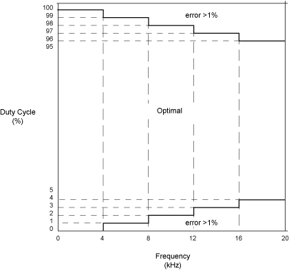
When duty cycle is below 5% or above 95%, depending on the frequency, the deviation is above 1% as illustrated in the graphic below:
