The embedded I/O function allows configuration of the controller inputs and outputs.
The following table describes the digital inputs of the M218 controllers:
|
Reference |
Total number of digital inputs |
Number of fast Inputs |
|---|---|---|
|
TM218LDA16DRN |
9 |
2 reduced fast inputs (I0, I1) |
|
TM218LDA24DRN |
14 |
2 reduced fast inputs (I0, I1) |
|
TM218LDA24DRHN |
14 |
4 (I0 to I3) |
|
TM218LDD24DUPHN |
14 |
4 (I0 to I3) |
|
TM218LDAE24DRHN |
14 |
4 (I0 to I3) |
|
TM218LDA40DRN |
24 |
2 reduced fast inputs (I0, I1) |
|
TM218LDA40DRPHN |
24 |
4 (I0 to I3) |
|
TM218LDD40DUPHNB |
24 |
4 (I0 to I3) |
|
TM218LDAE40DRPHN |
24 |
4 (I0 to I3) |
|
TM218LDA40DR2HN |
24 |
4 (I0 to I3) |
|
TM218LDA40DR4PHN |
24 |
4 (I0 to I3) |
|
TM218LDA60DRN |
36 |
2 reduced fast inputs (I0, I1) |
Accessing the I/O Configuration Window
|
Step |
Description |
|---|---|
|
1 |
In the Devices tree, double-click Embedded Functions > IO. |
|
2 |
Select the I/O Configuration tab. |
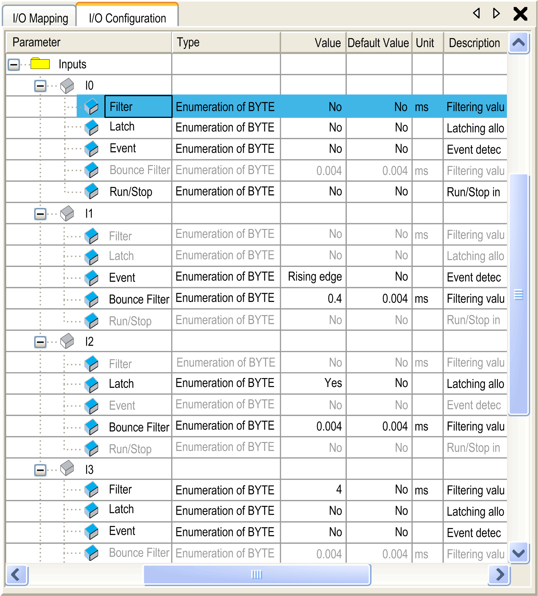
This figure shows the I/O Configuration tab for digital inputs:

I/O Mapping Window Description
The I/O Mapping window contains the following columns:
|
Column |
Description |
|---|---|
|
Variable |
Lets you map the channel on a variable. Double-click the icon to enter the variable name. If it is a new variable, the variable is created. It is also possible to map an existing variable with the variables Input Assistant by clicking the ... button. NOTE: New variables are automatically created on each channel according to the "Automatic I/O mapping" project option settings. |
|
Mapping |
Indicates if the channel is mapped on a new variable or an existing variable. |
|
Channel |
Name of the channel of the device. |
|
Address |
Address of the channel. |
|
Type |
Data type of the channel. |
|
Default Value |
Value taken by the Output when the controller is in a STOPPED state. Double-click to change the default value. |
|
Unit |
Unit of the channel value. |
|
Description |
Description of the channel. |
Digital Input Configuration Parameters
For each digital input, you can configure the following parameters:
|
Parameter |
Value |
Description |
Constraint |
|---|---|---|---|
|
Filter |
No 3 ms* 12 ms |
Reduces the effect of noise on a controller input. |
Available if Latch and Event are disabled. In the other cases, this parameter is disabled and its value is None. |
|
Latch |
No* Yes |
Allows incoming pulses with amplitude widths shorter than the controller scan time to be captured and recorded. |
This parameter is only available for the fast inputs I0 to I3. NOTE: not available for the reduced Fast Inputs I0 and I1. Available if Event disabled AND Run/Stop disabled. |
|
Event |
No* Rising edge Falling edge Both edges |
Event detection |
This parameter is only available for the fast inputs I0 to I3. NOTE: not available for the reduced Fast Inputs I0 and I1. Available if Latch disabled AND Run/Stop disabled. |
|
Bounce Filter |
0.004 ms* 0.4 ms 1.2 ms 4 ms |
Reduces the effect of bounce on a controller input. |
Available if Latch is enabled or Event is enabled. In the other cases, this parameter is disabled and its value is 0.004. |
|
Run/Stop |
No* Yes |
The Run/Stop input can be used to run or stop a program in the controller |
Select one of the inputs to use as the Run/Stop input. |
|
* Parameter default value |
|||
NOTE: The selection is grey and inactive if the parameter is unavailable.