These expansion modules have a built-in removable screw terminal block for the connection of inputs, outputs, and power supply.
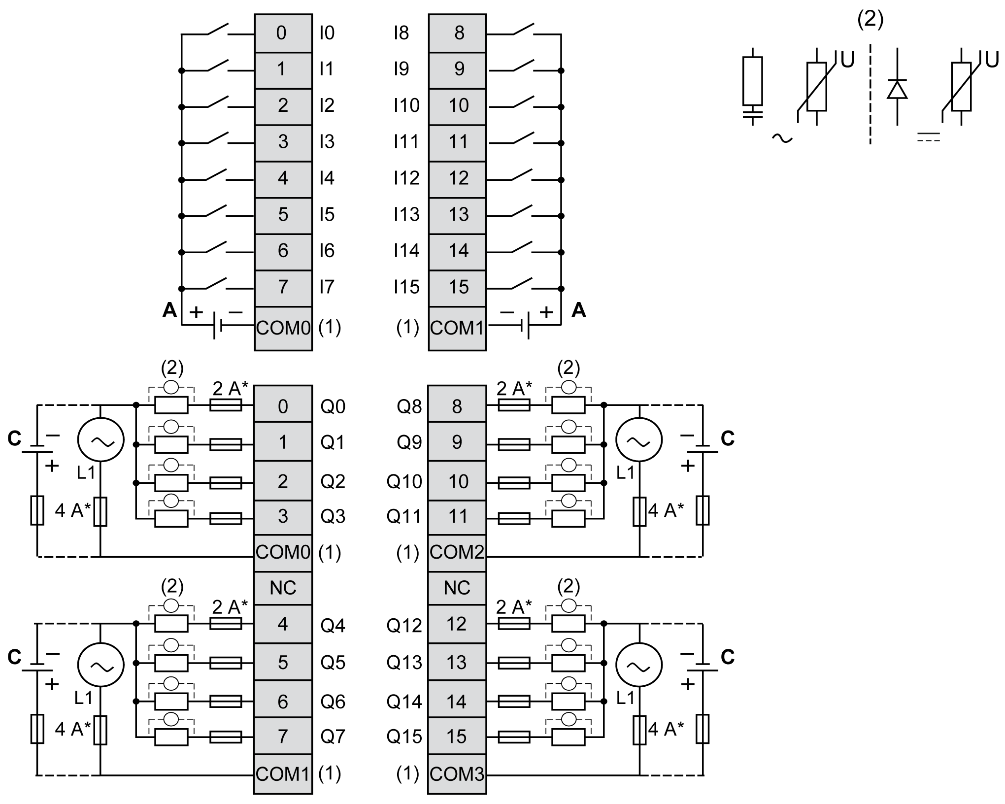
The following figure illustrates the connections between the inputs and outputs, the sensors and actuators, and their commons for a positive logic:

* Type T Fuse
(1) The inputs COM0, COM1, outputs COM0, COM1, COM2, and COM3 terminals are not connected internally.
(2) To improve the life time of the contacts, and to protect from potential inductive load damage, connect a free wheeling diode in parallel to each inductive DC load or an RC snubber in parallel of each inductive AC load.
A Sink wiring (positive logic)
C Source wiring (positive logic)
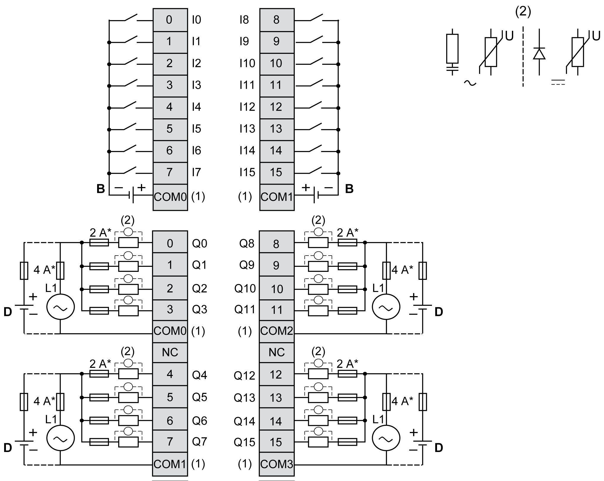
The following figure illustrates the connections between the inputs and outputs, the sensors and actuators, and their commons for a negative logic:

* Type T Fuse
(1) The inputs COM0, COM1 and outputs COM0, COM1, COM2, and COM3 terminals are not connected internally.
(2) To improve the life time of the contacts, and to protect from potential inductive load damage, connect a free wheeling diode in parallel to each inductive DC load or an RC snubber in parallel of each inductive AC load.
B Source wiring (negative logic)
D Sink wiring (negative logic)
For information about 24 Vdc power supply, refer to DC Power Supply Characteristics.
|
|
|
UNINTENDED EQUIPMENT OPERATION |
|
Do not connect wires to unused terminals and/or terminals indicated as “No Connection (N.C.)”. |
|
Failure to follow these instructions can result in death, serious injury, or equipment damage. |