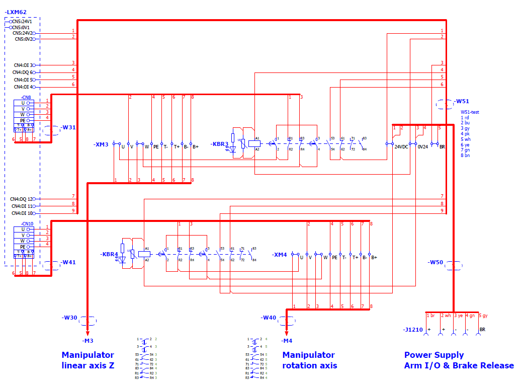
Wiring the Brake Release Button
Pin 5 of the cable (VW3E1169R050) on connector X1210 must be connected to the third digital input of the drive used for motor / axis 3 (CN4 pin 3 jumpered to pin 9) to be able to use the brake release button.
The connector X1210 transmits the signal of the brake release button from the robot to the controller.
The wires for 24 Vdc and 0 V of connector X1210 must be connected to CN5 of the drive (pin 1 and pin 2 of X1210 -> pin 1 of CN5, pin 3, and pin 4 of X1210 -> pin 2 of CN5).
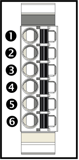
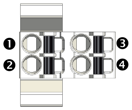
Pin Assignment of VW3E1169R050 Cable
|
Representation |
Pin |
Designation |
Description |
|---|---|---|---|
|
1 |
24 Vdc (in) |
Supply voltage |
|
2 |
24 Vdc (in) |
Supply voltage |
|
|
3 |
0 V |
Supply voltage |
|
|
4 |
0 V |
Supply voltage |
|
|
5 |
24 Vdc |
Signal if brake release button is pressed. |
Connectors of Lexium 62 Servo Drive
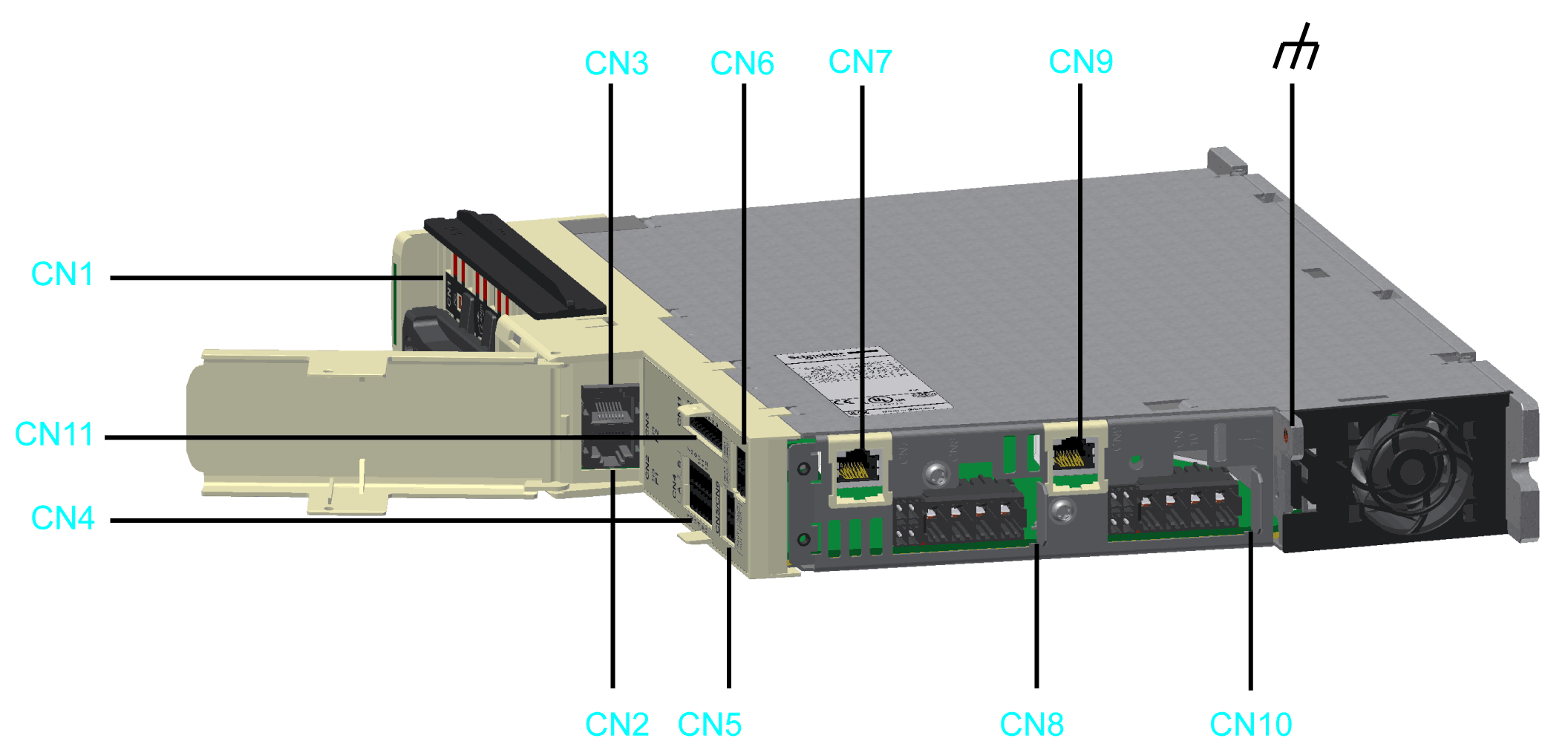
CN4 Connector of Lexium 62 Single Drive
Pin 3 must be connected.
CN4 Connector of Lexium 62 Double Drive
Pin 3 respectively pin 9 must be connected.
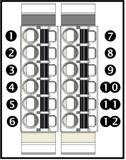
CN5 Connector of Lexium 62 Servo Drive
Pin 1 and pin 2 must be connected.
Two double drives are used to power the four axes of the SCARA.
o1. Double drive A -> Motor/Axis A
o1. Double drive B -> Motor/Axis B
o2. Double drive A -> Motor/Axis C
o2. Double drive B -> Motor/Axis D
Connect pin 5 of connector X1210 to CN4 pin 3 of the second double drive.
The wires to control and monitor the contactors of the additional circuit must be connected to the OnBoard I/Os of drive C and drive D (CN4 pin 4 and pin 10 opening contacts, pin 5 and pin 11 closing contacts, pin 6 and pin 12 control signal for the contactors). Therefore, both drives need attached OnBoard I/Os within the device tree.
To help to ensure correct functionality, the pins used as outputs must also be configured as outputs inside the controller. (Drive C / drive D -> LXMx2IO_InOutTP: Parameter IO5_Mode must be set to output and parameter IO4_Mode must be set to input).
Example: